Eureka AIR delivers breakthrough ideas for toughest innovation challenges, trusted by R&D personnel around the world.

Robot Compliance Device

Active Publication Date: 2010-05-06
NEXEN GROUP INC
View PDF23 Cites 3 Cited by
  • Summary
  • Abstract
  • Description
  • Claims
  • Application Information

AI Technical Summary

Benefits of technology

[0015]All figures are drawn for ease of explanation of the basic teachings of the present invention only; the extensions of the figures with respect to number, position, relationship, and dimensions of the parts to form the preferred embodiments will be explained or will be within the skill of the art after the following teachings of the present invention have been read and understood. Further, the exact dimensions and dimensional proportions to conform to specific force, weight, strength, and similar requirements will likewise be within the skill of the art after the following teachings

Problems solved by technology

However, the elastic bodies may bend in an undesired manner as a result of a large insertion force required in assembly.
As a result, assembly can not be performed properly, since the first part held by the lower plate is liable to be inclined due to undesired angular misalignment between the axes resulting from compression of the elastic bodies along the axis of the first part.
However, undesired angular misalignment still exists during assembly, for the elastic bodies are still compressed along the axis of the first part.
Aside from the above problems, the above compliance devices suffer from the common disadvantages including but not limited to being expensive, having complicated structures and having limited applications such as limited working force ranges.

Method used


Image

  • Robot Compliance Device
  • Robot Compliance Device
  • Robot Compliance Device

Examples


Embodiment Construction

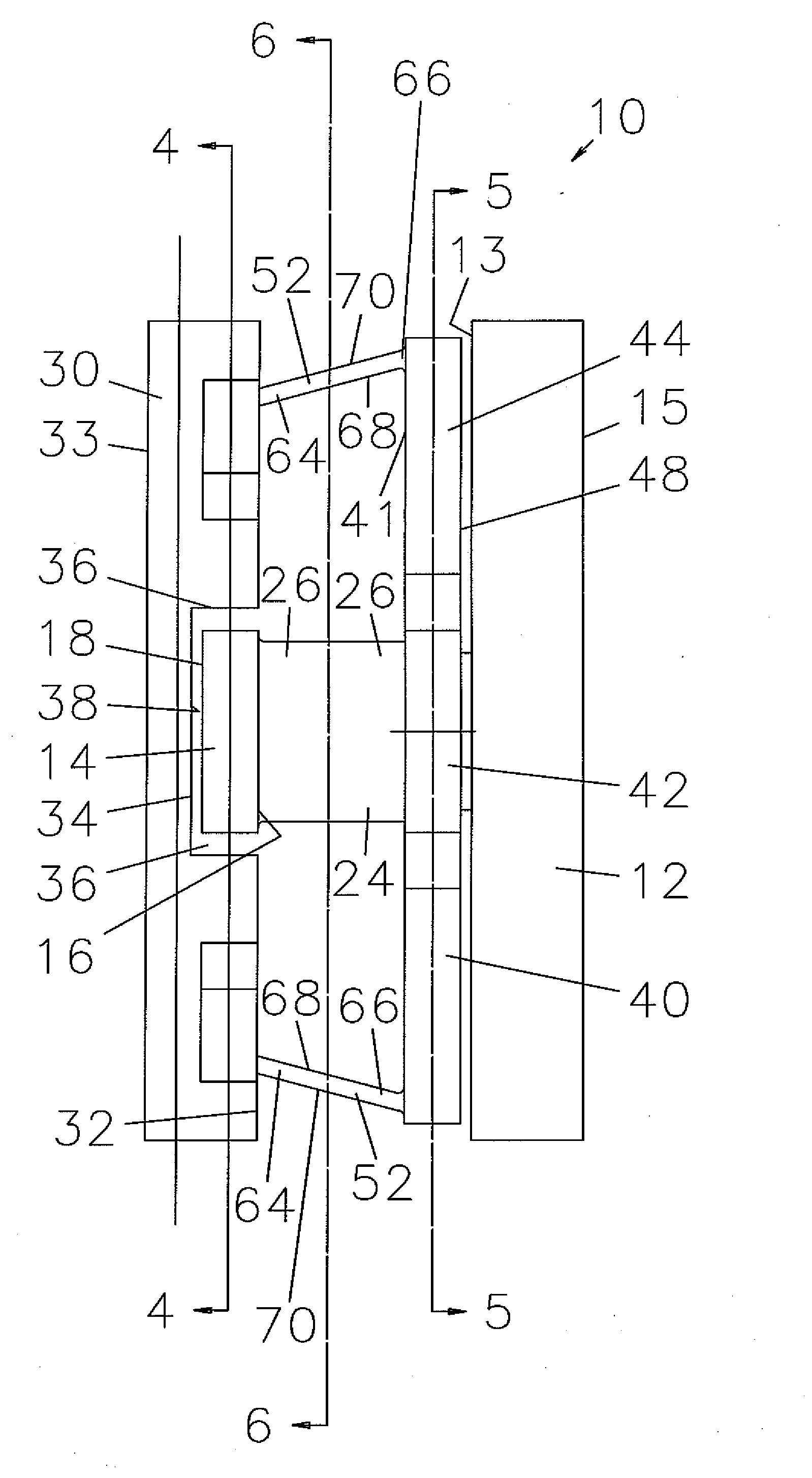
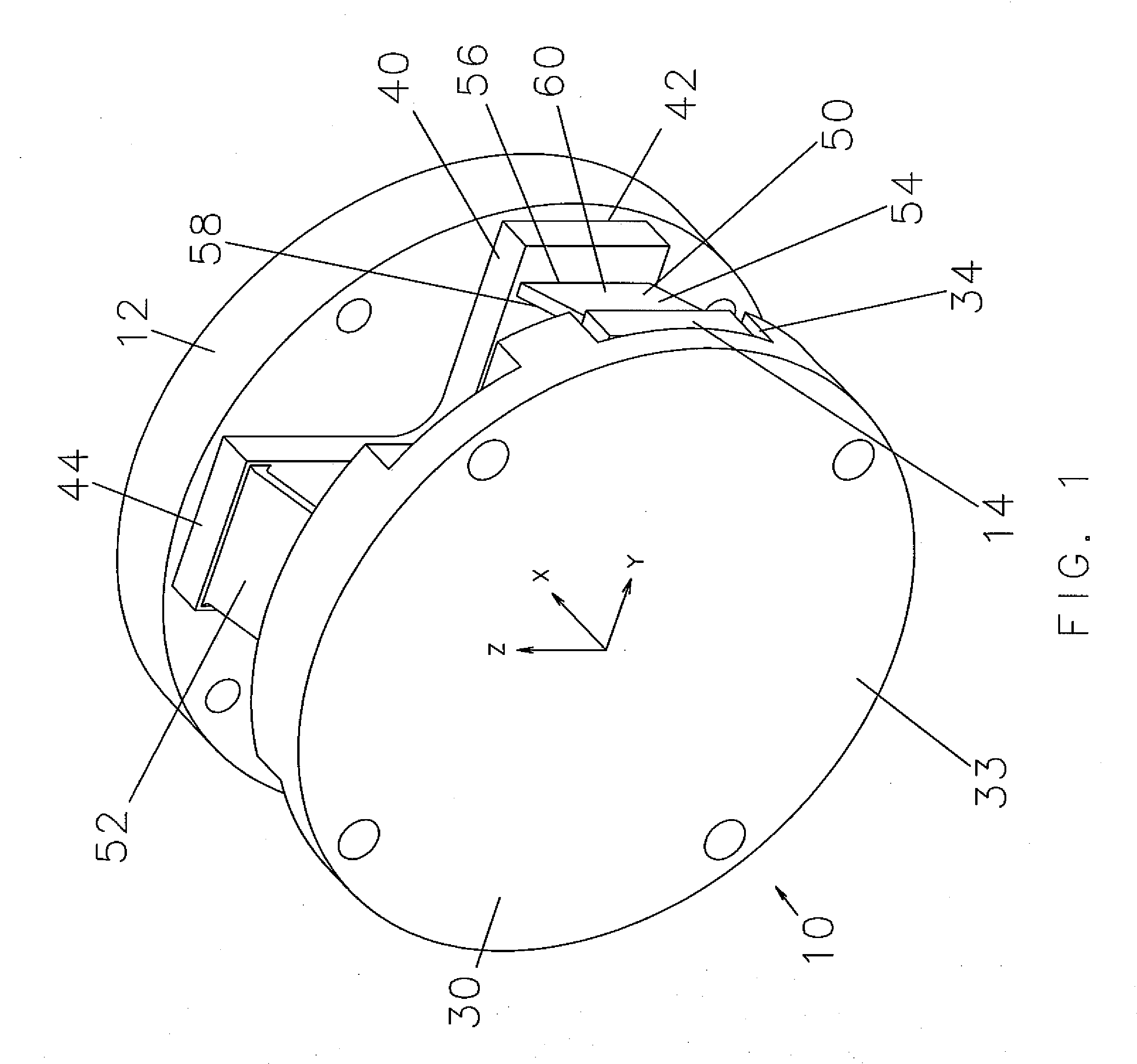
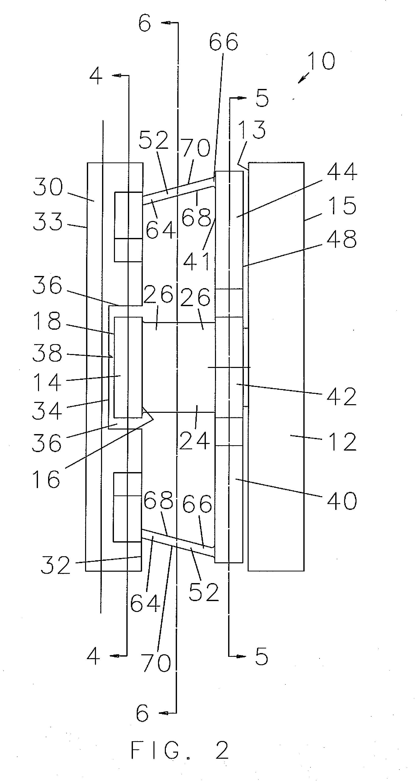
[0017]A robot compliance device according to the preferred teachings of the present invention is shown in the drawings and generally designated 10. According to the preferred form shown, robot compliance device 10 includes a first disc 12 that has an inner face 13 and an outer face 15 parallel to and spaced from inner face 13 along a first axis X. First disc 12 has circular cross sections between inner face 13 and outer face 15.

[0018]A beam 14 in the most preferred form shown as a right parallelepiped is spaced from inner face 13 of first disc 12 along first axis X. Specifically, beam 14 includes an inner surface 16 facing inner face 13 of first disc 12 and parallel to and spaced from inner face 13 of first disc 12 along first axis X. Beam 14 further includes an outer surface 18 parallel to and spaced from inner surface 16 along first axis X and facing away from first disc 12. Beam 14 further includes first and second ends 20 spaced along a second axis Y perpendicular to first axis ...


PUM


Abstract

A robot compliance device includes first and second discs (12, 30) spaced along a first axis (X). A column (24) is interconnected between the first disc (12) and a beam (14) intermediate the first and second discs (12, 30). A compliance member (40) is mounted around the column (24) between the first disc (12) and the beam (14). First and second canted resilient plates (50) are interconnected between the compliance member (40) and the beam (14) and spaced from each other along a second axis (Y) perpendicular to the first axis (X) and are at a first acute angle with and spaced from the first axis (X). Third and fourth canted resilient plates (52) are interconnected between the second disc (30) and the compliance member (40) and spaced from each other along a third axis (Z) perpendicular to the first and second axes (X, Y) and are at a second acute angle with and spaced from the first axis (X). When one of the first and second discs (12, 30) is subjected to a force acting in a direction not coincident to the first axis (X), the first, second, third and fourth canted resilient plates (50, 52) respectively deform along the second axis (Y) and the third axis (Z) with the compliance member (40) moving along the second and third axes (Y, Z) responsive to the deforming of the first, second, third, and fourth canted resilient plates (50, 52), with the compliance member moving relative to the first axis (X) and with the object rotating about an object center of compliance during insertion of the object into the workpiece.

Description

BACKGROUND OF THE INVENTION[0001]The present invention relates to a robot compliance device and, more particularly, to a robot compliance device that has a simple structure and that can avoid undesired angular misalignment during operation.[0002]Robots are widely utilized in many industries for various purposes. In one application, robots are utilized to assemble a first part such as a precise shaft, a pin, or a bearing into a hole of a second part. Many compliance devices have been developed to compensate misalignment between axes of the first and second parts due to machine inaccuracy, vibration, or tolerance during assembly. A typical compliance device generally includes an upper plate attached to a bracket of a robot, a lower plate carrying the first part, and a plurality of elastic bodies between the upper and lower plates. When the first part is subjected to a reactive force resulting from the misalignment between the axes of the first and second parts, the elastic bodies are ...

Claims


Application Information

Patent Timeline
IPC IPC(8): B25J18/00G01D21/00B25J19/00
CPCB25J17/0208Y10T74/20305
Inventor WEISS, KEVIN B.
Owner NEXEN GROUP INC
Why Eureka
Eureka Blog
Learn More