Cushion to frame assembly mechanism
- Summary
- Abstract
- Description
- Claims
- Application Information
AI Technical Summary
Benefits of technology
Problems solved by technology
Method used
Image
Examples
first embodiment
1. First Embodiment of Cushion to Frame Assembly Mechanism
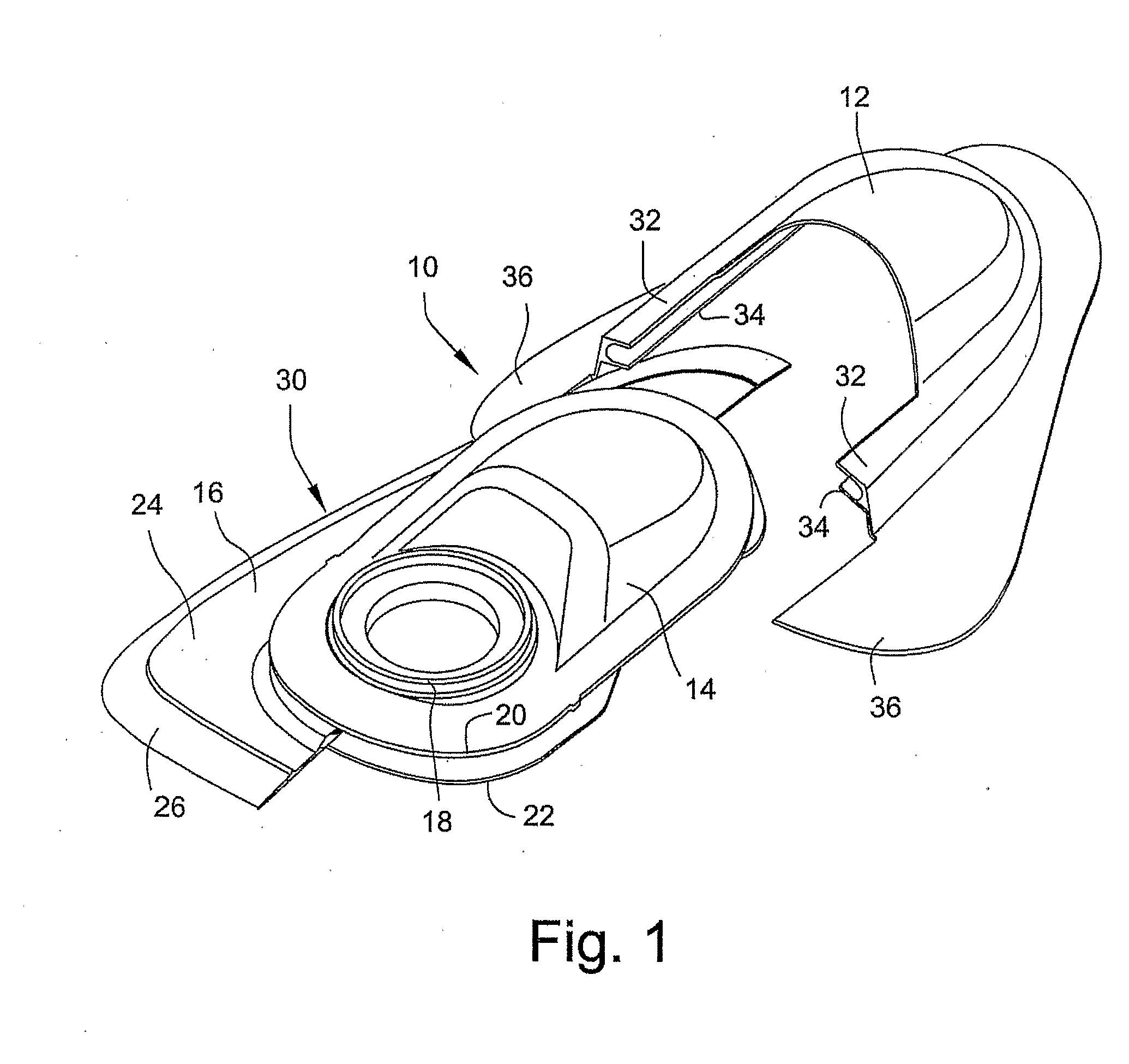
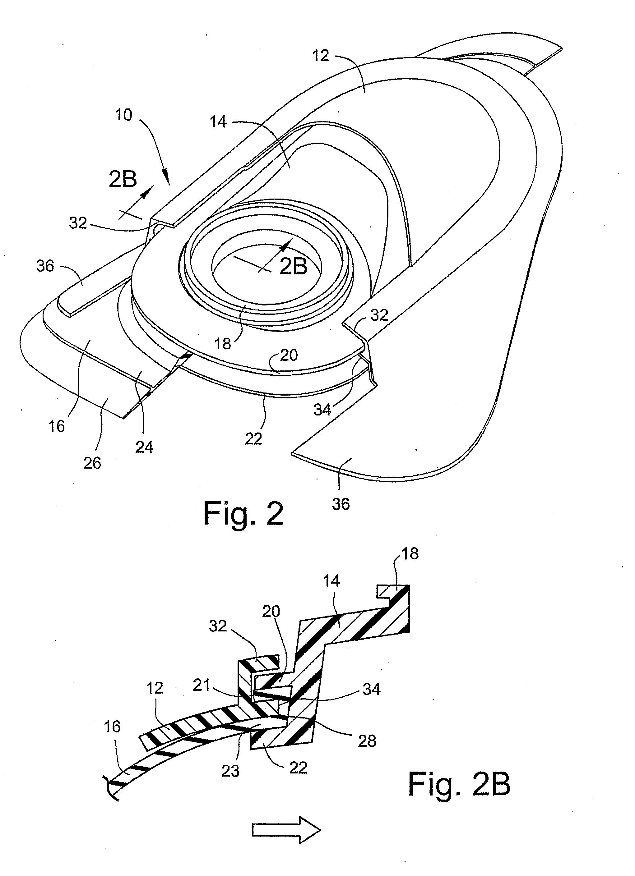
[0082]FIGS. 12, and 2B illustrate a mask assembly 10 including a cushion to frame assembly mechanism according to an embodiment of the present invention. In the illustrated embodiment, the cushion to frame assembly mechanism includes a slide-on frame clip 12 that is adapted to removably connect the frame 14 to the cushion 16.
[0083]Specifically, the frame 14 includes a main body that provides an opening 18 for communicating with an inlet conduit. At least a portion of the frame perimeter includes spaced apart upper and lower retaining wall portions 20, 22. The cushion 16 (only half being shown) includes a cushion wall 24 and a face-contacting portion 26, e.g., membrane. The cushion wall 24 includes a central opening with upper and lower walls 21, 23 that define an inner edge 28 (see FIG. 2B). As shown in FIG. 1, the frame 14 is received within the central opening of the cushion 16 so that the inner edge 28 of the cushion 16 is...
second embodiment
2. Second Embodiment of Cushion to Frame Assembly Mechanism
[0087]FIGS. 3 and 4 illustrate a mask assembly 210 including a cushion to frame assembly mechanism according to another embodiment of the present invention. In the illustrated embodiment, the cushion to frame assembly mechanism includes a skeleton frame 212 that is adapted to removably interlock with a cushion / frame sub-assembly 230.
[0088]Specifically, a frame and a cushion are integrally molded in one-piece to provide a cushion / frame sub-assembly 230. In an embodiment, the cushion / frame sub-assembly 230 may be constructed of liquid silicone rubber (LSR). However, other suitable materials may be used.
[0089]The cushion / frame sub-assembly 230 includes an upper wall 220 that provides an opening 218 for communicating with an inlet conduit. An annular wall 240 surrounds the opening 218. A side wall 224 extends from the upper wall 220 and leads to a face contacting portion 226. In an embodiment, the face contacting portion 226 has...
third embodiment
3. Third Embodiment of Cushion to Frame Assembly Mechanism
[0096]FIGS. 6-8 illustrate a mask assembly 410 including a cushion to frame assembly mechanism according to another embodiment of the present invention. In the illustrated embodiment, the cushion to frame assembly mechanism includes a skeleton frame 412 that is adapted to removably interlock with a cushion / frame sub-assembly 430.
[0097]Specifically, a frame 414 and a cushion 416 are formed separately from one another and then interlocked to provide a cushion / frame sub-assembly 430. As shown in FIG. 6, the cushion 416 includes a side wall 424 and a face contacting portion 426 extending from the side wall 424. In an embodiment, the face contacting portion 426 has a double wall construction, e.g., membrane and underlying support cushion. Also, in an embodiment, the cushion 416 is constructed of liquid silicone rubber (LSR). However, other suitable materials may be used.
[0098]The frame 414 includes an upper wall that provides an o...
PUM
 Abstract
Description
Claims
Application Information
 - R&D
- Intellectual Property
- Life Sciences
- Materials
- Tech Scout
- Unparalleled Data Quality
- Higher Quality Content
- 60% Fewer Hallucinations
Browse by: Latest US Patents, China's latest patents, Technical Efficacy Thesaurus, Application Domain, Technology Topic, Popular Technical Reports.
© 2025 PatSnap. All rights reserved.Legal|Privacy policy|Modern Slavery Act Transparency Statement|Sitemap|About US| Contact US: help@patsnap.com


