Surgical clamp pads with deflecting elements

a technology of deflecting elements and clamp pads, which is applied in the field of surgical instruments, can solve the problems of slipping devices off of the clamped vessel, trauma to the clamped vessel at the clamping site, and the vessel is especially prone to slippag

Inactive Publication Date: 2005-09-13
VITALTEC INT
View PDF31 Cites 226 Cited by
  • Summary
  • Abstract
  • Description
  • Claims
  • Application Information

AI Technical Summary

Benefits of technology

[0006]The present invention meets these and other needs and provides for replaceable surgical clamp pads or inserts having an attaching structure for attachment of the insert to the jaw, and an elastomeric cushion secured to the attaching structure. The cushion includes a clamping surface for engagement with a vessel or other body tissue, and a deflecting element, at least a portion of which is embedded within the cushion, between the attaching structure and the clamping surface. The deflecting element can also include a second portion that extends from the clamping surface.

Problems solved by technology

Conventional surgical clamps or clips made of metal or other rigid materials can cause trauma to the clamped vessel at the clamping site.
These devices are prone to slipping off of the clamped vessel.
This can be especially problematic in situations where, due to obstructions, a vessel has been clamped with only the distal tips of the clamp jaws.
In such situations, the vessel can be especially prone to slipping in the direction of the distal tips.
While the Haller device is less traumatic to a vessel than other occlusion devices, it nevertheless has the disadvantage of traumatizing the outer layer of the vessel.
The hard teeth of this device serve to resist movement of a clamped vessel laterally of the jaw, but do so at increased risk of trauma to the vessel.

Method used


Image

  • Surgical clamp pads with deflecting elements
  • Surgical clamp pads with deflecting elements

Examples


first embodiment

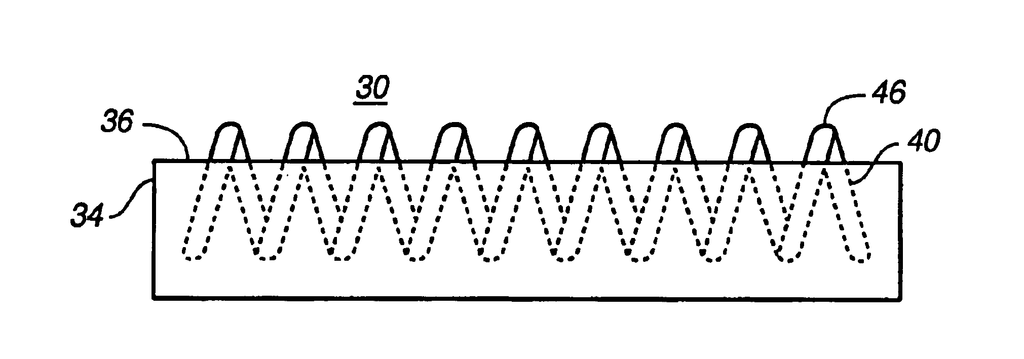
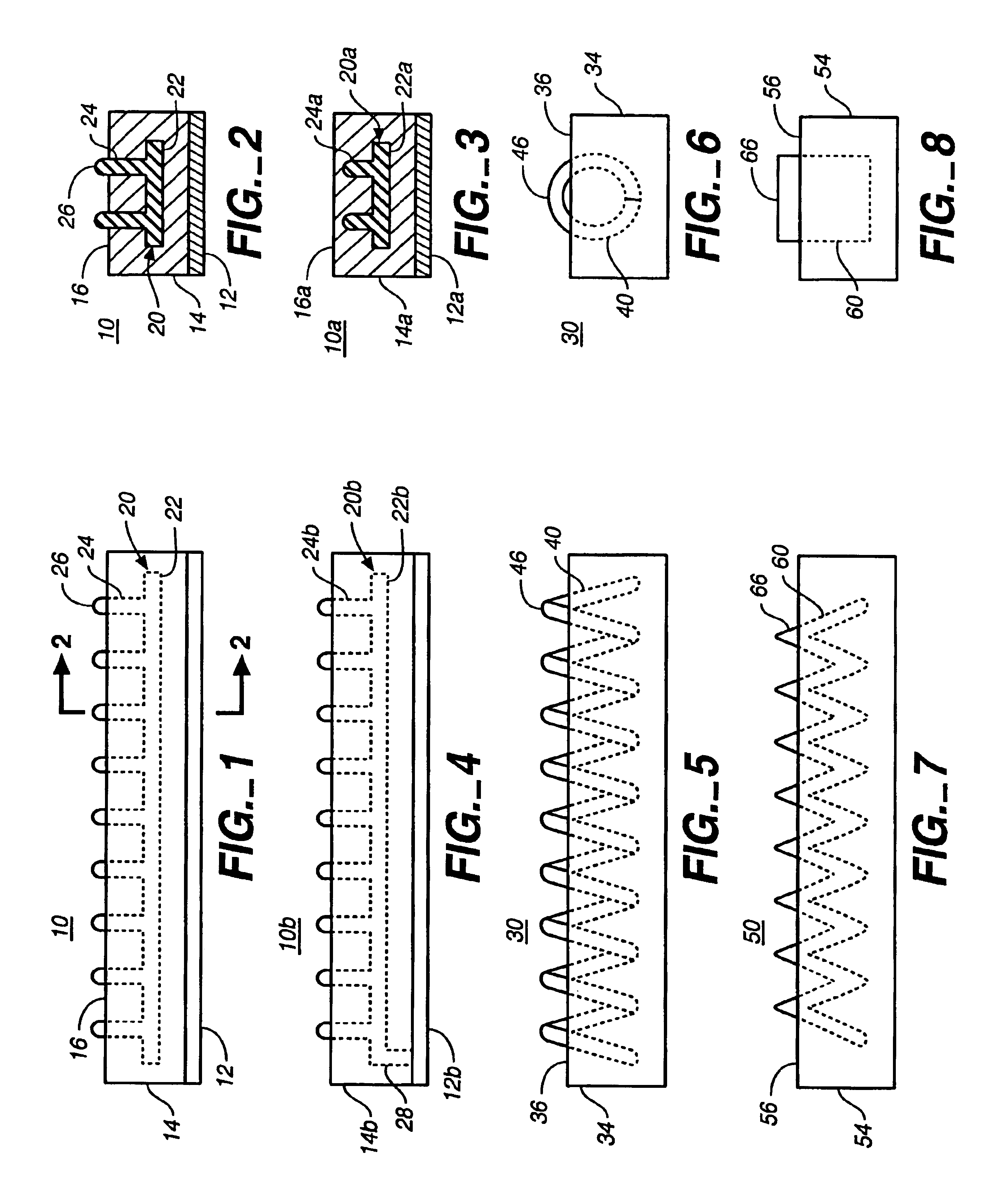
[0019]FIGS. 1 and 2 depict a replaceable surgical clamp pad or insert according to the invention. Insert 10 includes attachment member 12 for attaching the insert to the jaw of a jaw-type occlusion device. Elastomeric cushion 14 is secured to the attachment member. Cushion 14 includes a clamping surface 16 for engagement with a vessel or other body tissue, opposite the attachment member. Deflecting element 20 is embedded in the cushion.

[0020]Elastomeric cushion 14 can be formed of a variety of materials known in the art that are resiliently deflectable and which provide cushion to a clamped vessel. Such materials include, but are not limited to, natural rubber, neoprene, urethane, ethyl vinyl acetate foam, or silicone or silicone foam. It is desirable that the material be a thermoplastic elastomer suitable for liquid injection molding and having a 20A-40 A shore durometer rating. Such thermoplastic elastomers include silicone, such as GE 6040 or silicone foam GE RTF762, polyurethane...

second embodiment

[0028]FIG. 4 shows the invention. Like the embodiment of FIGS. 1 and 2, insert 10b includes deflecting element 20b embedded in cushion 14b, with the deflecting element comprising an elongate plate 22b having columns 24b extending therefrom. In this embodiment, however, one end of plate 22b is maintained in a fixed relationship to attaching structure 12b. As shown, strut 28 extends from attaching structure 12b and is fixedly secured to one end of plate 22b.

[0029]In this embodiment, the degree of deflection of plate 22b under a clamping load increases along the length of plate, from minimal deflection at the end fixed to strut 28 to maximal deflection at the end of the plate furthest from the strut. The result is that the deformability of the cushion as a whole varies along the length of the cushion. In operation, such variation provides greater flexibility in vessel occlusion, as the relative degree of deformation and corresponding resistance to such deformation can be controlled by...


PUM


Abstract

A replaceable pad or insert for attachment to the jaw of a jaw-type occlusion device. The insert includes an elastomeric cushion with a deflecting element embedded in the cushion, providing for improved gripping of a clamped vessel while minimizing trauma to the vessel.

Description

BACKGROUND OF THE INVENTION[0001]The present invention relates generally to surgical instruments for occluding a vessel or other body conduit, and more particularly, to replaceable pads or inserts for attachment to jaw-type occlusion devices.[0002]Instruments for occluding blood vessels and other body conduits are well known. Conventional surgical clamps or clips made of metal or other rigid materials can cause trauma to the clamped vessel at the clamping site. A number of atraumatic instruments have been developed for reducing trauma to a vessel during occlusion. In particular, conventional surgical clamps and clips have been adapted to include jaw surfaces containing resilient members or pads. These devices are prone to slipping off of the clamped vessel. This can be especially problematic in situations where, due to obstructions, a vessel has been clamped with only the distal tips of the clamp jaws. In such situations, the vessel can be especially prone to slipping in the directi...

Claims


Application Information

Patent Timeline
Patent Type & Authority Patents(United States)
IPC IPC(8): A61B17/122A61B17/12A61B17/28A61B17/00A61B17/03A61B17/08
CPCA61B17/122A61B17/08A61B2017/00778A61B2017/00858A61B2017/2825A61B2017/2829
Inventor BUELNA, TERRENCE
Owner VITALTEC INT
Why Eureka
Try Eureka