
Cushion for a Patient Interface

Active Publication Date: 2008-01-10
RESMED LTD
View PDF98 Cites 227 Cited by
  • Summary
  • Abstract
  • Description
  • Claims
  • Application Information

AI Technical Summary

Problems solved by technology

However, gas pressurized in the range of 4-20 cmH2O can be noisy and uncomfortable.
Poorly fitting masks can provide an inadequate seal against leak.
After wearing a mask all night, some patients can have pressure sores on their faces, especially in such sensitive regions as the nasal bridge.

Method used


Image

  • Cushion for a Patient Interface
  • Cushion for a Patient Interface
  • Cushion for a Patient Interface

Examples


Embodiment Construction

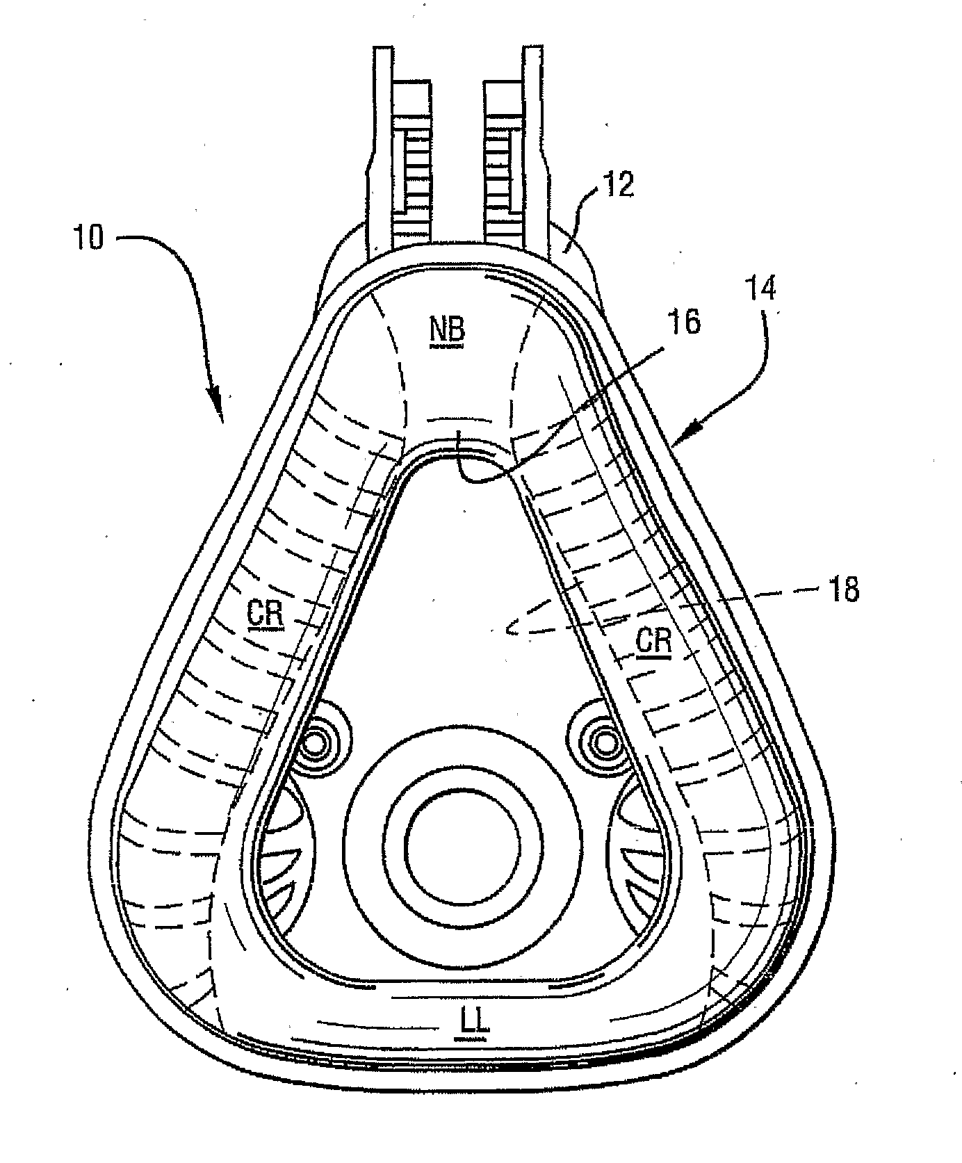
[0024] In a dual walled cushion, the outer wall (outer membrane) can define a sealing structure and the inner wall (inner membrane) can define a support structure. A seal can form when a patient's face is lightly pressed against the outer membrane. However, the outer membrane will easily flex upon contact with the patient's face. The inner membrane is generally thicker and more rigid than the outer membrane. When a patient's face presses against the outer membrane, the gap between the two membranes reduces. At a larger contact force, there may be no gap between the two membranes. With a yet higher contact force, the inner membrane will also begin to flex. In response to a contact force from a patient's face to the cushion, the cushion will provide a reaction force from the cushion to the patient's face. The size and direction of the resultant reaction force in a particular region will depend upon the face and cushion properties in that region.

[0025]FIG. 7 illustrates a patient inte...


PUM


Abstract

A cushion for a patient interface includes an outer membrane providing a sealing structure adapted to form a seal with the patient's face in use and an underlying membrane generally spaced away from the outer membrane. The underlying membrane provides a support structure for the outer membrane. The outer membrane and the underlying membrane each have an inner edge which defines an aperture to receive the patient's nose in use. The underlying membrane is segmented along its inner edge.

Description

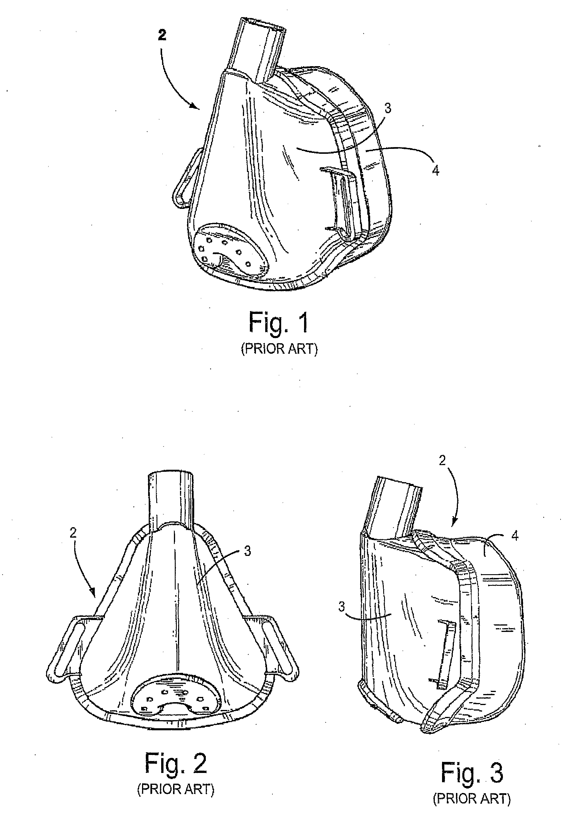
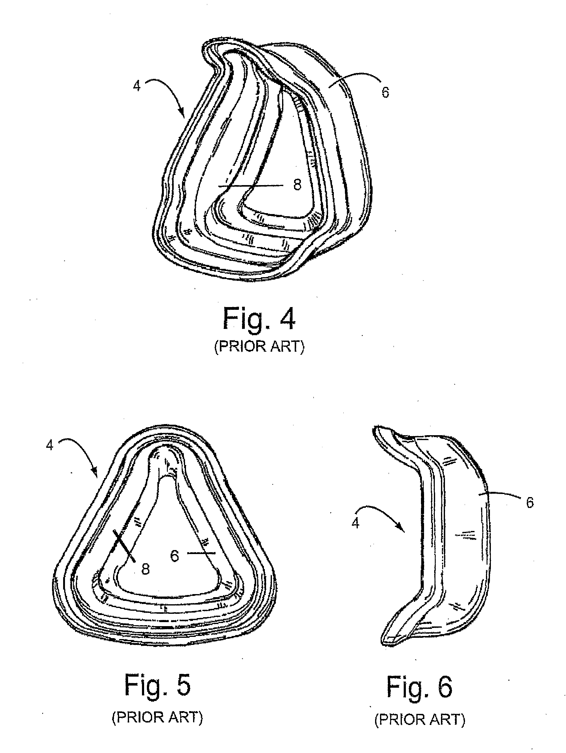
CROSS-REFERENCE TO THE APPLICATIONS [0001] This application claims the benefit of Australian Provisional Application No. 2004902979 filed Jun. 3, 2004, incorporated herein by reference in its entirety. FIELD OF THE INVENTION [0002] The invention relates to treatment of sleep disordered breathing. In particular, the invention relates to a cushion for a patient interface used for treatment of sleep disordered breathing. BACKGROUND OF THE INVENTION [0003] The use of nasal Continuous Positive Airway Pressure (nasal CPAP) to treat Sleep Disordered Breathing (SDB), for example Obstructive Sleep Apnea (OSA), was invented by Sullivan (See U.S. Pat. No. 4,944,310). Such treatment is typically accomplished using a source of air at positive pressure (e.g., a blower or flow generator) connected to a patient interface (e.g., a mask) via an air delivery conduit. To maintain a suitable pressure at the entrance to the patient's airways, it is necessary to provide a suitable seal between the patient...

Claims


Application Information

Patent Timeline
IPC IPC(8): A61M16/06A62B7/00
CPCA61M16/06A61M16/0622A61M16/0616A61M16/0633A61M16/0605A61M2016/0661
Inventor WORBOYS, DAVID JOHNLYNCH, SUSAN ROBYN
Owner RESMED LTD
Learn More