
Cleaning device, charging device and image forming apparatus including the same

Active Publication Date: 2010-05-13
KYOCERA DOCUMENT SOLUTIONS INC
View PDF5 Cites 5 Cited by
  • Summary
  • Abstract
  • Description
  • Claims
  • Application Information

AI Technical Summary

Benefits of technology

[0008]The present invention provides a cleaning device capable of cleaning of a charging member. The present invention also provides an image forming apparatus including the cleaning device.

Problems solved by technology

However, there arises a problem of the physical adhesion of the residual material to the charging roller, which is caused by the imperfect cleaning of the surface of the photosensitive drum.
Moreover, a partial whitening of the surface of the charging roller causes nonuniformity in charging in a corresponding portion of the surface of the photosensitive drum.
As described above, the physical adhesion of the external additive for the toner to the surface of the charging roller becomes an obstacle to uniform and suitable charging of the surface of the photosensitive drum.
As a result, nonuniformity in charging of the surface of the photosensitive drum is inhibited.
Therefore, it is difficult to maintain the cleaning performance of the brush roller over a long period of time.

Method used


Image

  • Cleaning device, charging device and image forming apparatus including the same
  • Cleaning device, charging device and image forming apparatus including the same
  • Cleaning device, charging device and image forming apparatus including the same

Examples


examples

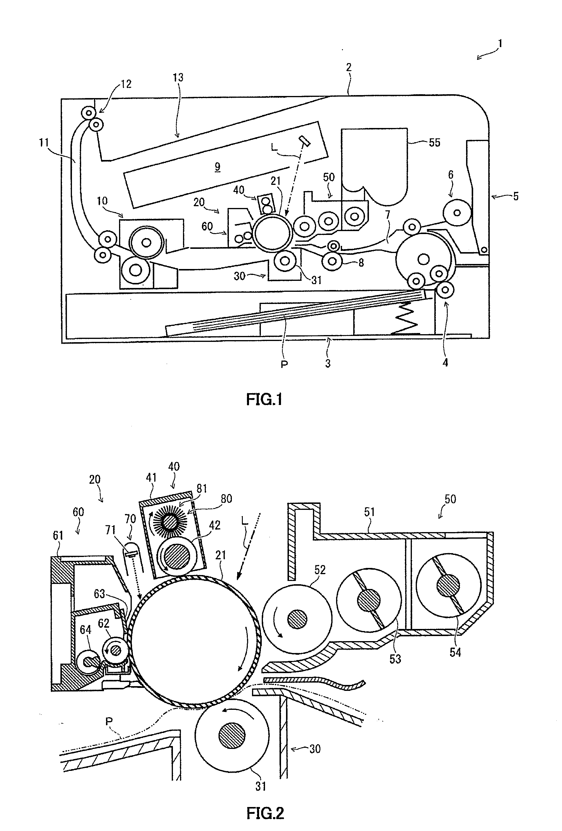
[0050]A comparative experiment between a case where an embodiment of the herein described cleaning element was utilized (example) and a case where cleaning did not occur (comparative example) was conducted using the printer 1 as shown in FIG. 1.

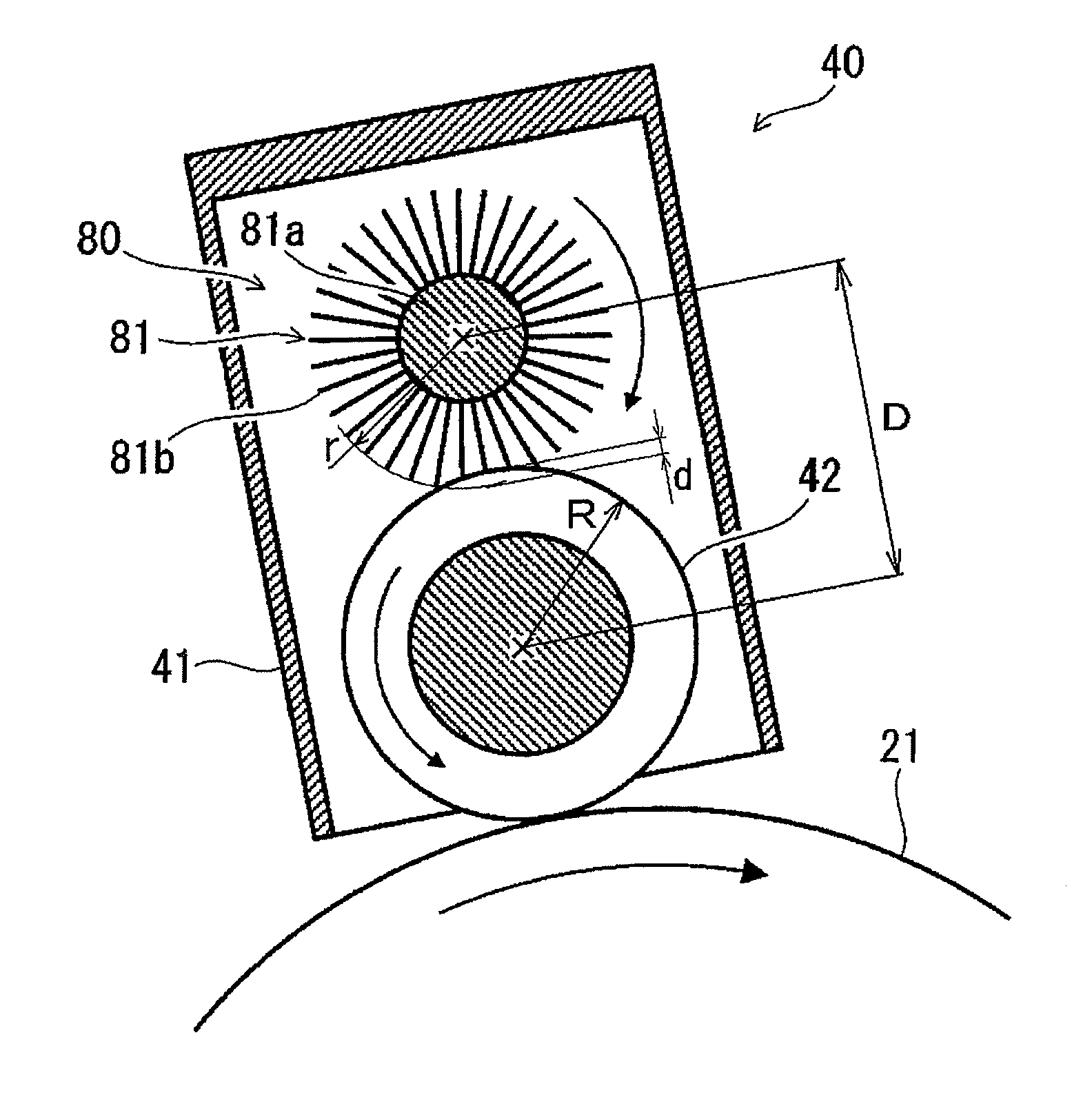
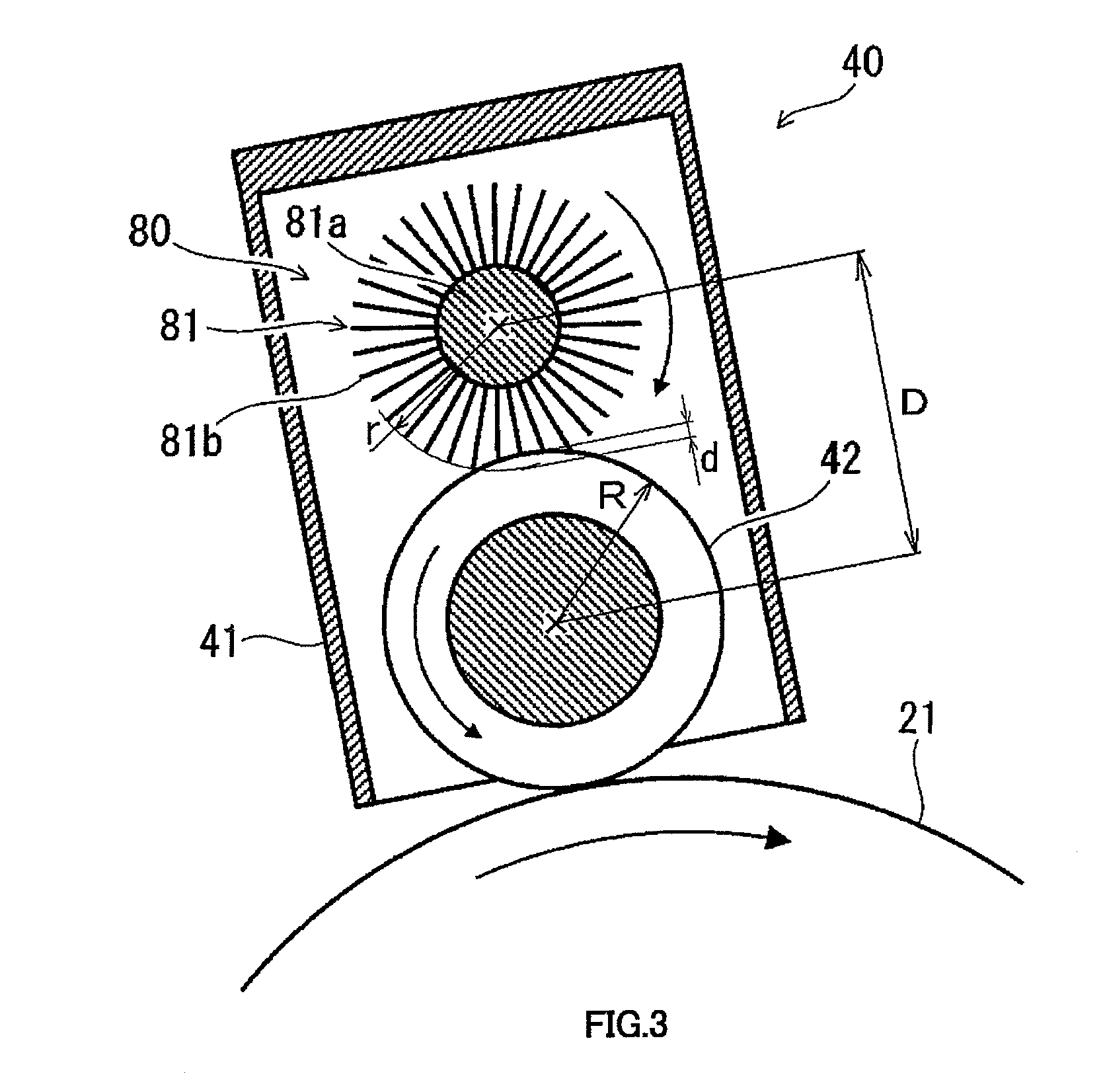
[0051]For the case where the herein described cleaning element was utilized (example), titanium oxide (EC-100 fabricated by Titan Kogyo Ltd.) corresponding to the external additive for the toner used in the printer 1 was used. As a method of bonding the inorganic microparticles 82 to the tips of the brush filaments 81b, the above-described high voltage bonding method was used. As conditions of carrying out the high voltage bonding method, the rotation speed of the brush roller was 200 rpm, the voltage applied between the brush roller and the metal roller was 3 to 5 kV, the fitting amount of the brush roller 81 to the metal roller was 1.0 mm. The brush filaments used on the brush roller 81 were filaments of 6-nylon (conductive fiber) having a ...


PUM


Abstract

A cleaning element for a printer is described. The cleaning element may include a brush, which is used for an image forming apparatus. The brush roller may include a support structure and brush filaments extending therefrom. The brush filaments may be configured to contact a surface of a-member to be cleaned. Thus, it is possible to provide a cleaning lement capable of removing material adhering to the surface of the member to be cleaned. The cleaning element is capable of providing long-term effective cleaning of a member of an image forming apparatus during extended use.

Description

INCORPORATION BY REFERENCE[0001]This application is based upon and claims the benefit of priority from the corresponding Japanese Patent application No. 2008-289422, filed Nov. 12, 2008, the entire content of which is incorporated herein by reference.FIELD OF THE INVENTION[0002]The present invention relates to a cleaning device used for an image forming apparatus such as a copying machine or a printer. The present invention also relates to a charging device and an image forming apparatus which include the cleaning device.BACKGROUND OF THE INVENTION[0003]In an image forming apparatus using electrophotography, image formation processes as follows are generally performed. Specifically, a surface of a photosensitive drum (image bearing member) is uniformly charged with a predetermined polarity and potential by a charging device. Then, an electrostatic latent image of an original image is formed by an exposure device. Next, the electrostatic latent image is developed by a developing devi...

Claims


Application Information

Patent Timeline
IPC IPC(8): G03G15/02
CPCG03G15/0225
Inventor MIYAMOTO, HIDETOSHI
Owner KYOCERA DOCUMENT SOLUTIONS INC
Learn More