Sealing device for rotary fluid machine, and rotary fluid machine
- Summary
- Abstract
- Description
- Claims
- Application Information
AI Technical Summary
Benefits of technology
Problems solved by technology
Method used
Image

Examples
first embodiment
[0058]A compressor according to a first embodiment of the present invention will be described below with reference to FIGS. 1 to 4.
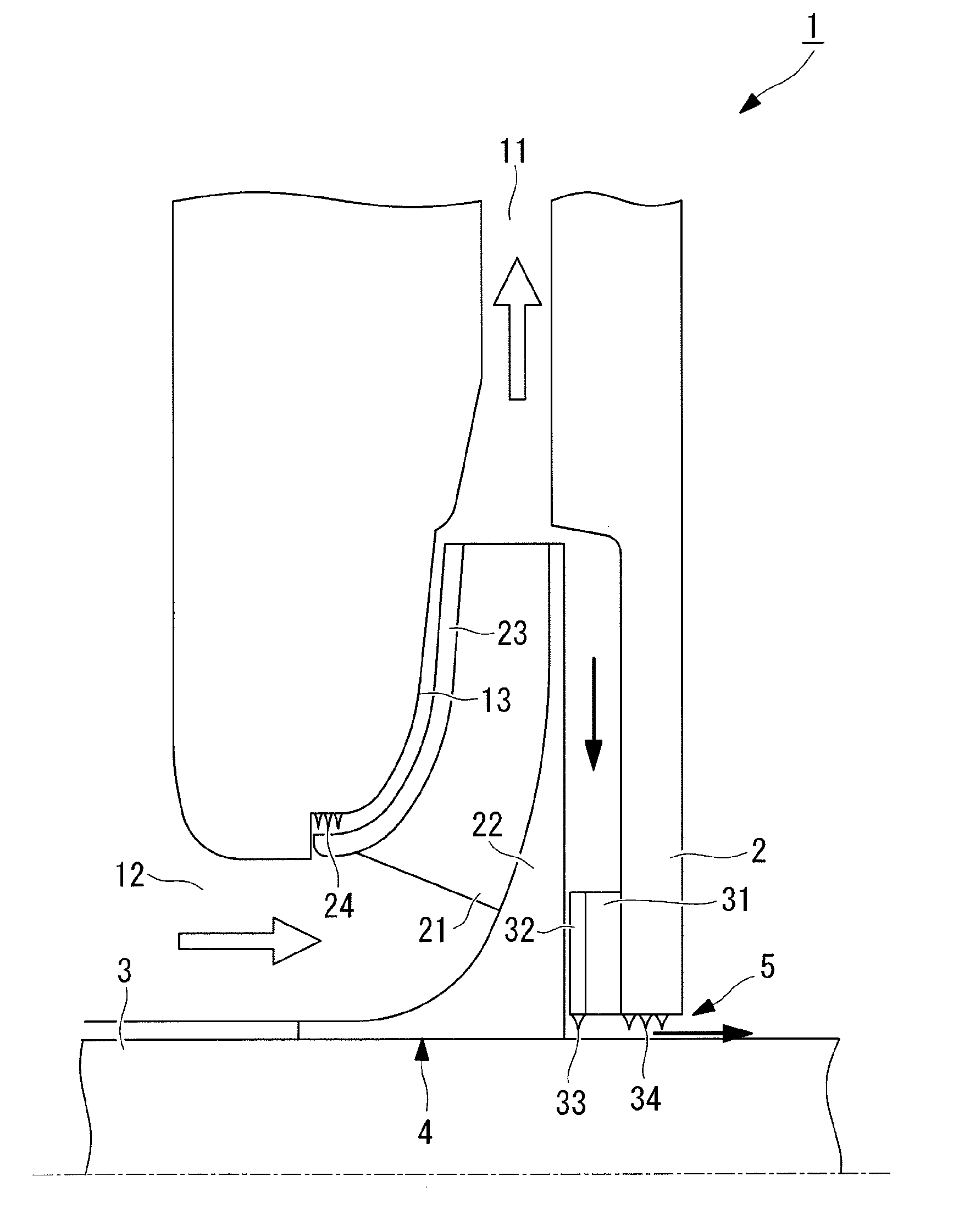
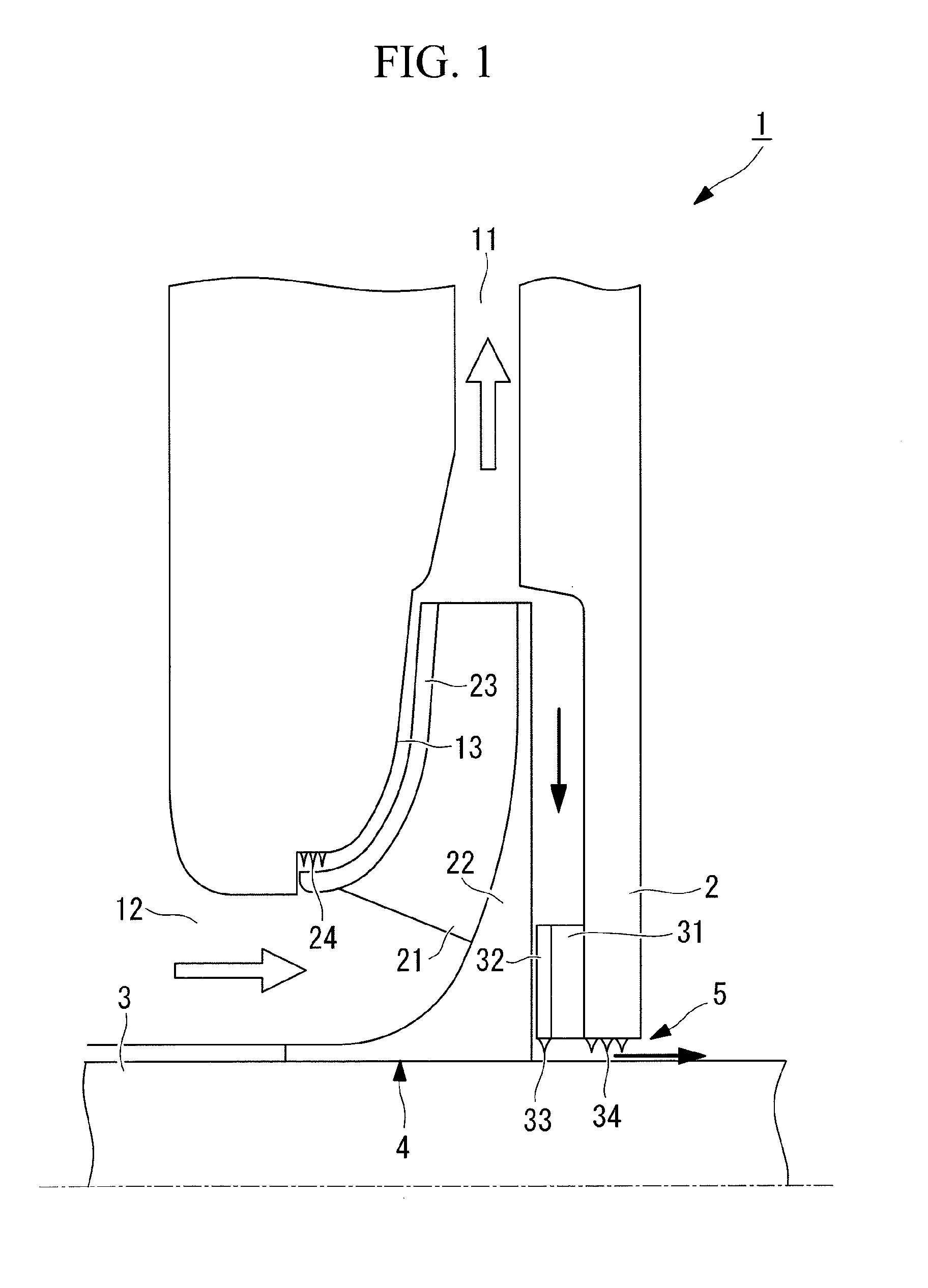
[0059]FIG. 1 is a schematic view for explaining the structure of the compressor according to this embodiment.
[0060]A compressor (rotary fluid machine) 1 is supplied with rotary driving force from an external power source, such as a motor, to supply high-pressure gas. In this embodiment, a description will be given of a single-stage compressor of the present invention.
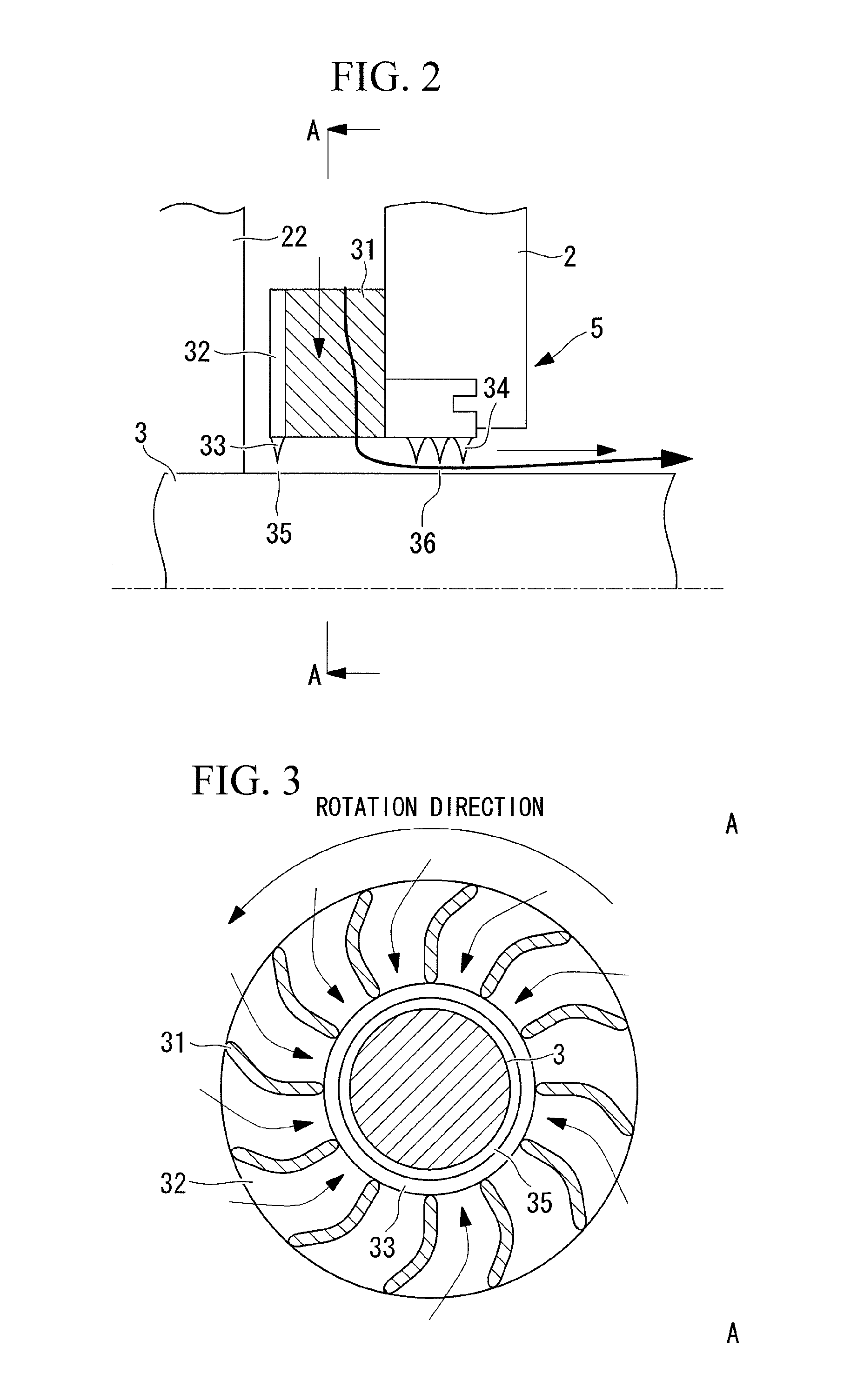
[0061]As shown in FIG. 1, the compressor 1 includes a housing 2, a rotary shaft 3, an impeller (impeller) 4, and a sealing device 5.
[0062]The housing 2 rotatably holds the rotary shaft 3 and the impeller 4 therein and includes the sealing device 5 on an inner surface thereof. Further, the housing 2 includes a high-pressure-side flow passage 11 that supplies high-pressure gas to the outside, a low-pressure-side flow passage 12 that supplies low-pressure gas (for example, air at atmospheric pr...
second embodiment
[0136]Next, a second embodiment of the present invention will be described with reference to FIGS. 8 to 10.
[0137]Although the basic structure of a compressor of this embodiment is the same as that of the first embodiment, the structure of a sealing device is different from that of the first embodiment. Therefore, in this embodiment, only the structure of the sealing device and components surrounding it will be described with reference to FIGS. 8 to 10, and a description of the other components will be omitted.
[0138]FIG. 8 is a schematic view for explaining the structure of the sealing device in the compressor according to this embodiment.
[0139]Note that identical reference numerals are given to the same components as those of the first embodiment, and a description thereof will be omitted.
[0140]As shown in FIG. 8, a sealing device 305 of a compressor (rotary fluid machine) 301 includes a plurality of guide plates (guide parts) 331, a partition plate (partition part) 332, a first sea...
first modification
of Second Embodiment
[0160]Next, a first modification of the second embodiment of the present invention will be described with reference to FIGS. 11 to 13.
[0161]Although the basic structure of a compressor of this modification is the same as that of the second embodiment, the structure of a sealing device is different from that of the second embodiment. Therefore, in this modification, only the structure of the sealing device and components surrounding it will be described with reference to FIGS. 11 to 13, and a description of the other components will be omitted.
[0162]FIG. 11 is a schematic view for explaining the structure of the sealing device in the compressor according to this modification. FIG. 12 is a cross-sectional view for explaining the structure of the sealing device shown in FIG. 11 along the line D-D.
[0163]Note that identical reference numerals are given to the same components as those of the second embodiment, and a description thereof will be omitted.
[0164]As shown in...
PUM
 Abstract
Description
Claims
Application Information
 - R&D Engineer
- R&D Manager
- IP Professional
- Industry Leading Data Capabilities
- Powerful AI technology
- Patent DNA Extraction
Browse by: Latest US Patents, China's latest patents, Technical Efficacy Thesaurus, Application Domain, Technology Topic.
© 2024 PatSnap. All rights reserved.Legal|Privacy policy|Modern Slavery Act Transparency Statement|Sitemap