Antenna auto-configuration

a technology of auto-configuration and antenna, applied in the field of mobile telephony, can solve problems such as failures in the connection of antennas or transceivers, errors in beam pointing, and difficulty in correctly connecting antennas to signal processors, and achieve the effect of minimising overlap coverag

Active Publication Date: 2010-05-13
APPLE INC
View PDF18 Cites 65 Cited by
  • Summary
  • Abstract
  • Description
  • Claims
  • Application Information

AI Technical Summary

Benefits of technology

[0028]The directions in which the diversity pairs are pointed may not be known and so the frequencies to be used in the sectors needs to be determined. In an example of the invention, the frequencies are set by selecting one of the sectors, detecting the frequency of operation of a contiguous sector of an adjacent base station and setting the frequencies of the sectors according to the frequency re-use plan of the network, so as to minimise overlapping coverage on a common frequency channel

Problems solved by technology

Errors in beam pointing may occur or there may be faults in the antennas or the transceivers connected to them.
Furthermore, when constructing a base station, it is not easy to correctly connect the antennas to the signal processors.
The antennas are high above the housing of the signal processors and the cables for connecting them are heavy and difficult to manipulate.
The height of the tower makes the manipulation of the cables potentially dangerous especially in bad weather.
It is easy to incorrectly connect the cables to the antennas and signal processors.

Method used


Image

  • Antenna auto-configuration
  • Antenna auto-configuration
  • Antenna auto-configuration

Examples


Embodiment Construction

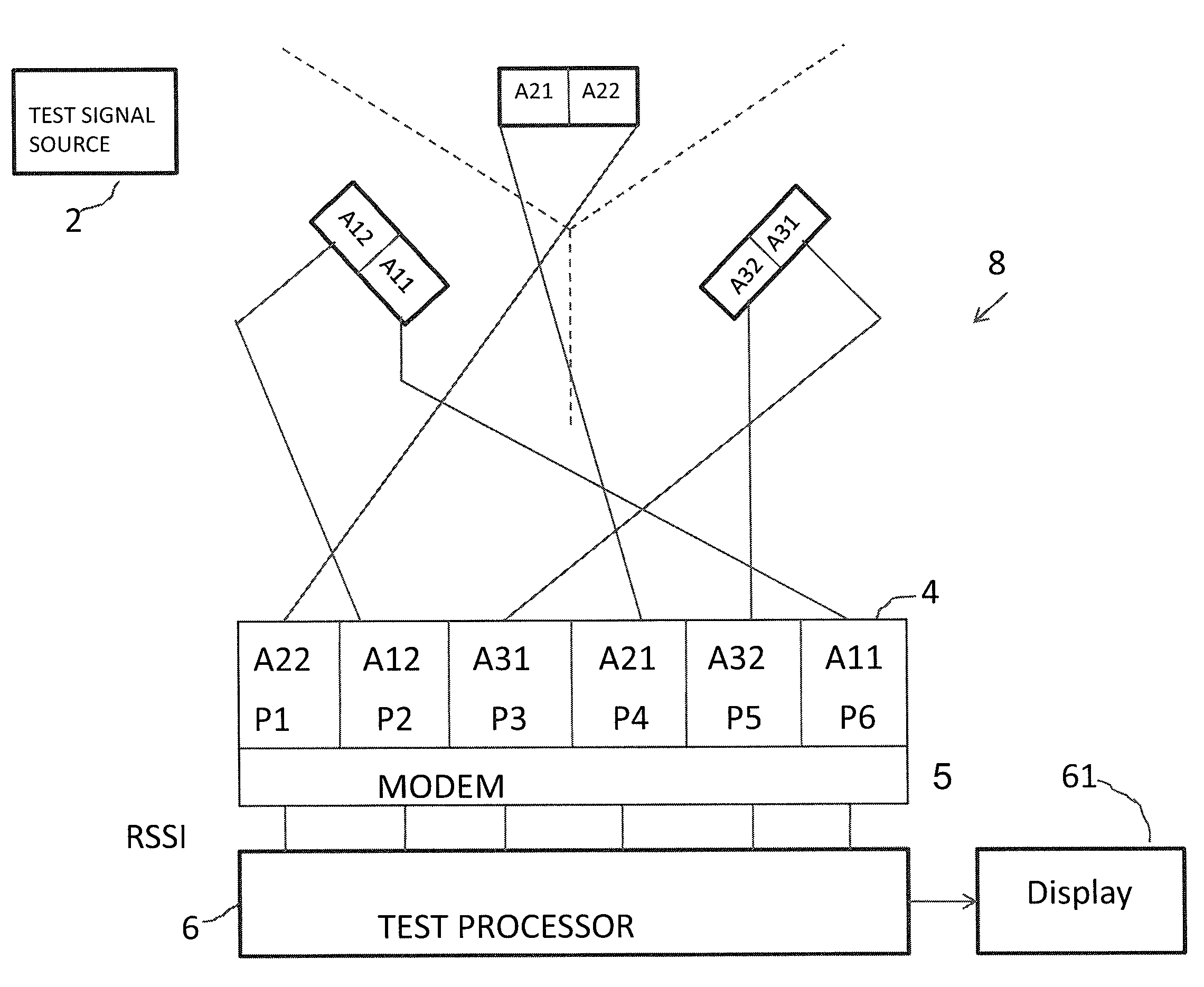
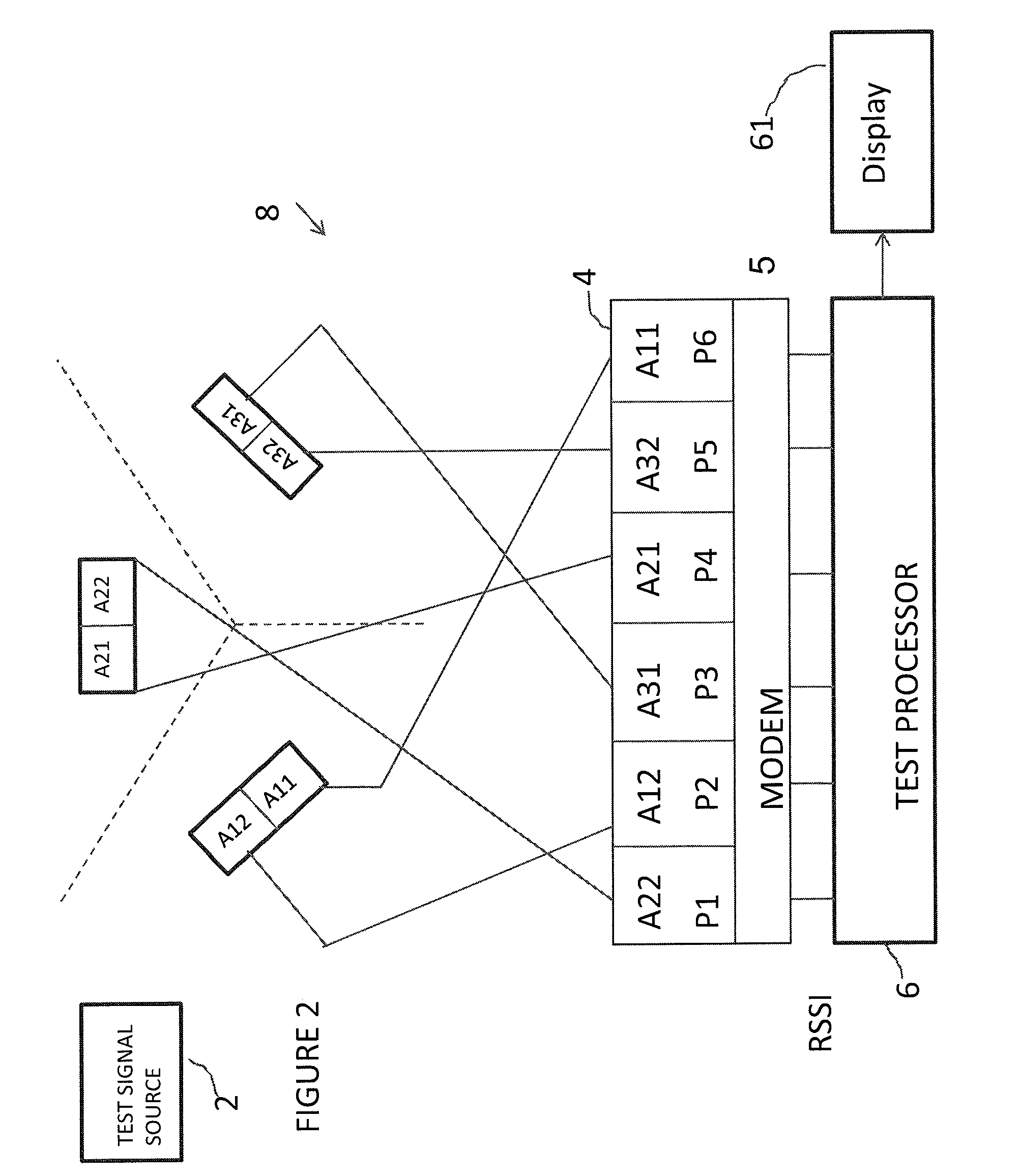
[0042]This illustrative description of FIGS. 1 to 8 assumes for ease of description that a base station has three sectors, each sector has two physical antennas which form a polarisation diversity pair, and each antenna has a single main beam with a fixed pointing direction. However the invention is not limited to that and as will be described many other arrangements are possible within the scope of the invention.

Determining Cable Configuration

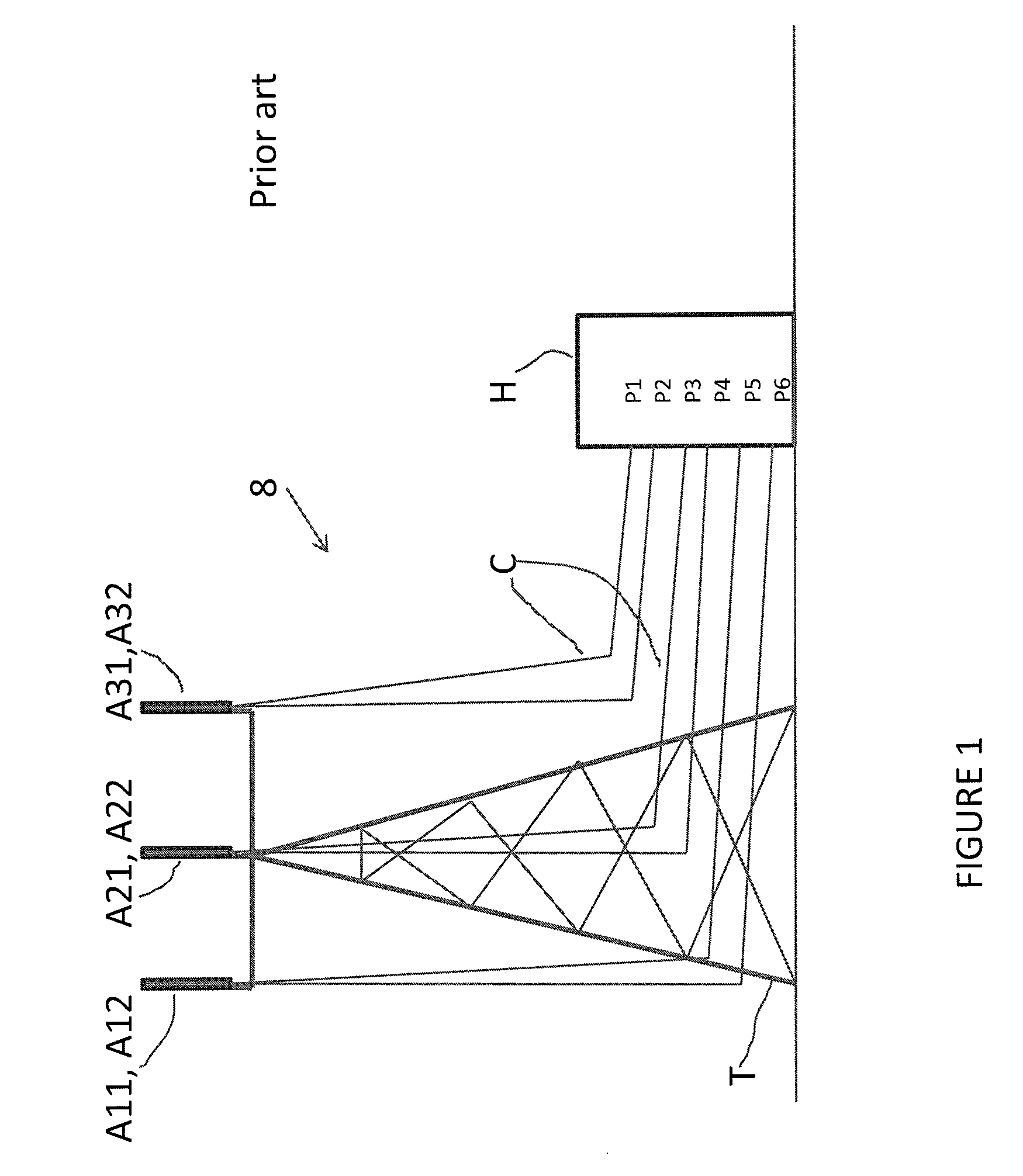
[0043]Referring to FIG. 1, an example of a conventional base station has a high tower supporting three diversity pairs of antennas: A11, A12; A21, A22; and A31, A32. The antennas of each pair are polarized at orthogonal polarizations for example + and −45 degrees. The six antennas are connected by respective cables to ports P1 to P6 of equipment housed in a cabinet or other housing H at ground level. Each port is connected to a signal processor which includes a radio transceiver and other signal processing circuitry. In the base station of FIG...


PUM


Abstract

A base station for use in a mobile telephony network includes an antenna arrangement coupled to a transceiver arrangement for producing a plurality of beams. A method of testing the base station comprises detecting at the transceiver arrangement the signal strengths of a test signal received via the beams; comparing and/or correlating the said signal strengths detected at the transceiver arrangement; and using the results of the comparisons and/or correlations to determine the configuration of the antenna arrangement and transceiver arrangement and/or to detect faults. The comparison of average signal strengths can be used to detect cabling faults, and beam errors. The correlation of un-averaged signal strengths can be used to determine which beams have the same polarisation. Beam pointing directions and the allocation of antennas to sectors can be determined by monitoring handovers of mobiles moving between cells. Frequencies may be allocated to sectors according to a frequency re-use scheme.

Description

FIELD OF THE INVENTION[0001]The present invention relates to mobile telephony. Embodiments of the invention relate to testing base stations of mobile telephony networks and to determining the configuration of a base station for use in a mobile telephony network.BACKGROUND OF THE INVENTION[0002]Mobile telephony networks are well known. Mobile telephony systems, in which user equipment such as mobile handsets communicate via wireless links to a network of base stations connected to a telecommunications network, have undergone rapid development through a number of generations. The initial deployment of systems using analogue modulation has been superseded by second generation digital systems, which are themselves currently being superseded by third generation digital systems such as UMTS and CDMA. Third generation standards provide for a greater throughput of data than is provided by second generation systems; this trend is continued with the proposal by the Third Generation Partnershi...

Claims


Application Information

Patent Timeline
Patent Type & Authority Applications(United States)
IPC IPC(8): H04W24/00
CPCH01Q1/1257H01Q3/267H04W16/02H04W24/00H04B17/318H04W28/04H04W36/08H04W88/08H04W24/06H04B7/06H04B7/10H04B17/17
Inventor URQUHART, ANDREW JAMESHALL, STEVEN RAYMONDGALE, SIMON JOHN
Owner APPLE INC
Why Eureka
Try Eureka