
Support stand for flat-panel display monitor and elevating support used for support stand

a technology for flat-panel display monitors and support stands, which is applied in the direction of machine supports, instruments, cabinet/cabinet/drawer covers, etc., can solve the problems of low impact resistance of support members, undesirable limiting effects, and easy abradement or damage of retaining pieces by external forces

Inactive Publication Date: 2010-05-20
HONG FU JIN PRECISION IND (SHENZHEN) CO LTD +1
View PDF11 Cites 20 Cited by
  • Summary
  • Abstract
  • Description
  • Claims
  • Application Information

AI Technical Summary

Benefits of technology

The present patent relates to a new support stand for a flat-panel display monitor and an elevating support. The technical effects of the patent include providing a support stand that overcomes the limitations of existing support stands, such as low impact resistance and limited adjusting range of the height of the monitor, by introducing a new elevating mechanism that improves the impact resistance and allows for greater adjusting range of the monitor's height. Additionally, the patent introduces a new support stand that includes a link bracket, rotatable bracket, and base member, which offer improved stability and flexibility compared to existing support stands.

Problems solved by technology

However, the retaining piece may be easily abraded or damaged by an exterior force.
As a result, the support member may have a low impact resistance and a undesirable limiting effect.

Method used


Image

  • Support stand for flat-panel display monitor and elevating support used for support stand
  • Support stand for flat-panel display monitor and elevating support used for support stand
  • Support stand for flat-panel display monitor and elevating support used for support stand

Examples


Embodiment Construction

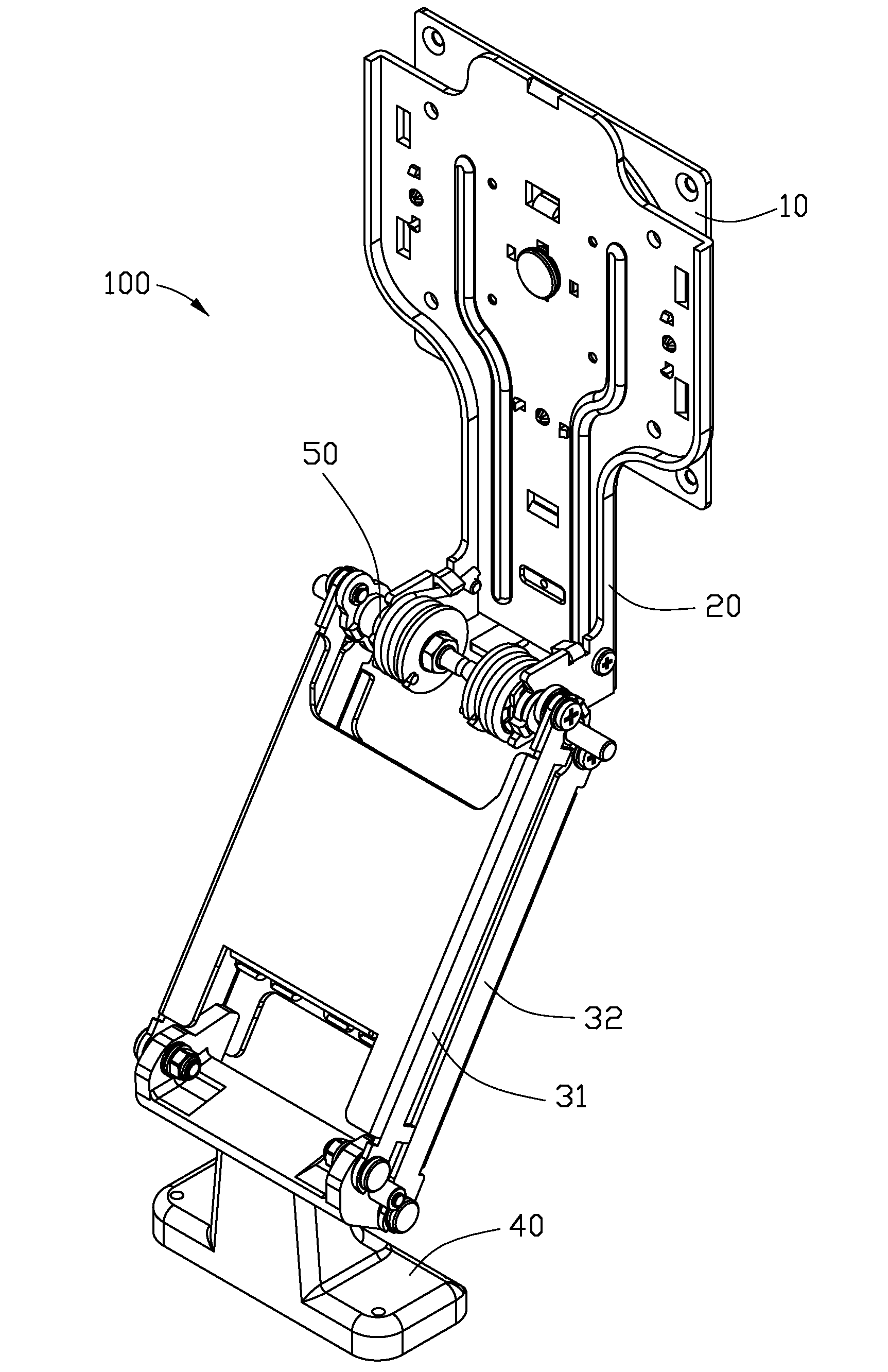
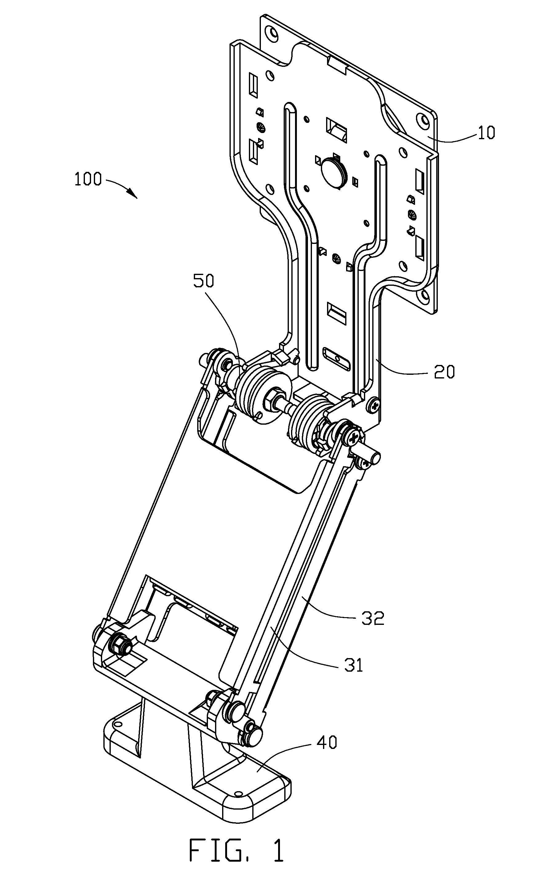
[0013]Referring to FIG. 1, a support stand 100 for a flat-panel display monitor includes a monitor bracket 10 to hold the flat-panel display monitor, a rotatable bracket 20 to fix the monitor bracket 10, a first link bracket 31, a second link bracket 32, a base member 40, and two hinge assemblies 50. The first and second link brackets 31, 32 are rotatably mounted between the rotatable bracket 20 and the base member 40 by the hinge assemblies 50.

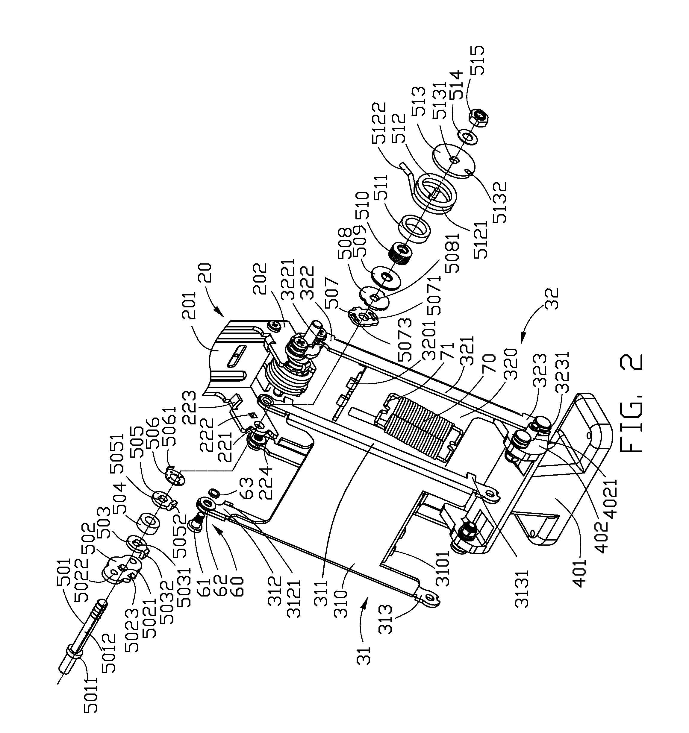
[0014]Referring also to FIG. 2, the rotatable bracket 20 includes a mounting board 201, and two side walls 202 extending from opposite sides of the mounting board 201. The mounting board 201 is fixed to the monitor bracket 10. Each of the side walls 202 defines a pivot hole 221, and a fixing groove 222 adjacent to the pivot hole 221. A restricting tab 223 is formed on each side wall 202 adjacent to the mounting board 201. Each of the side walls 202 also defines a curved groove 224 in an end away from the mounting board 201.

[0015]The first lin...


PUM


Abstract

The support stand for a flat-panel display monitor includes a rotatable bracket, a hinge assembly, a base member, a first and a second link brackets. The hinge assembly includes a connecting piece, and a pivotal shaft inserted through the connecting piece and the rotatable bracket. The pivotal shaft forms a restricting flange. The base member includes a supporting block forming a restricting pole. The first link bracket forms two limiting protrusions on the first and second end portions. The first end portions of the first and second link brackets are rotatably connected to the connecting piece, the second end portions of the first and second link brackets are rotatably connected to the supporting block. The two limiting protrusions of the first link bracket abut the restricting flange and the restricting pole respectively, thus adjusting the support stand to move between a first utmost position and a second utmost position.

Description

BACKGROUND[0001]1. Technical Field[0002]The present disclosure generally relates to support stands and elevating supports, particularly, to a support stand for a flat-panel display monitor and an elevating support.[0003]2. Description of Related Art[0004]Flat-panel display monitors, such as liquid crystal display monitors, offer advantages over cathode ray tube displays, such as reduced size, smaller weight, and better image quality. A viewing angle and height of the flat-panel display monitor can be adjusted without moving a support stand of the flat-panel display monitor because of its small weight.[0005]A typical support stand generally includes a bracket to attach to the flat-panel display monitor, a rotatable bracket to fix the bracket, an elevating mechanism, a support member, and a base member to mount the support member. A first end of the elevating mechanism is rotatably connected to the rotatable bracket and a second end of the elevating mechanism is supported by the suppo...

Claims


Application Information

Patent Timeline
Patent Type & Authority Applications(United States)
IPC IPC(8): F16M11/24F16M13/00
CPCF16M11/04F16M11/10F16M2200/063F16M11/24F16M2200/044F16M11/2092Y10S248/923
Inventor WANG, JIN-XIN
Owner HONG FU JIN PRECISION IND (SHENZHEN) CO LTD
Learn More