Printer

a printing machine and printing technology, applied in the field of printing machines, can solve the problems of increasing the weight of the carriage, the decrease of the durability of the carriage (printer), and the increase of the cost of manufacturing the printer, so as to reduce the abrasion or wear of the angle controlling member, the structure of the printer is simple, and the effect of reducing the cost of printing

Active Publication Date: 2012-05-29
BROTHER KOGYO KK
View PDF12 Cites 0 Cited by
  • Summary
  • Abstract
  • Description
  • Claims
  • Application Information

AI Technical Summary

Benefits of technology

[0008]However, in the case mentioned above, as described later in detail, respective flat surfaces of the non-movable slider and the movable slider that are opposed to a surface of the guide member are not always held in close contact with the surface of the guide member. Therefore, the movable and non-movable sliders are easily abraded or worn. It is therefore an object of the present invention to provide a printer that can solve this problem without complicating a structure of the printer.
[0010]In the printer in accordance with the present invention, the carriage is movable in the scanning direction) guided by the guide member. The carriage supports the angle-controlling member to be pivotable relative thereto. The angle-controlling member controls or adjusts the angular position of the carriage relative to the guide member in the state in which the at least one contact surface of the angle controlling member is in close contact with the surface of the guide member that extends in the scanning direction. Further, the pivotal position of the angle-controlling member relative to the carriage can be adjusted by the pivotal-position adjusting device. Therefore, an angular position of the recording head which is carried by the carriage can be controlled with a simple structure of the printer. In other words, a posture of the recording head relative to the recording medium that is opposed to the recording head can be controlled or adjusted with a simple structure of the printer.
[0011]Moreover, the angle-controlling member is supported by the carriage to be pivotable relative thereto and controls the angular position of the carriage relative to the guide member in the state in which the at least one contact surface of the angle-controlling member is in close contact with the surface of the guide member that extends in the scanning direction, so that the at least one contact surface of the angle-controlling member is kept in close contact with the surface of the guide member, even when the angular position of the carriage is changed. Therefore, an abrasion or wearing of the angle-controlling member is restrained, leading to increasing of a durability of the angle-controlling member. Furthermore, the angle-controlling member can be made of an inexpensive material without a high abrasion resistance.

Problems solved by technology

As disclosed in Patent Document 1, in a case where the sub carriage is supported by the main carriage to be pivotable relative thereto, a structure of the printer is complicated, so that not only a cost of manufacturing the printer increases, but also a weight of the carriage increases, leading to decreasing of a durability of the carriage (printer).
However, in the case mentioned above, as described later in detail, respective flat surfaces of the non-movable slider and the movable slider that are opposed to a surface of the guide member are not always held in close contact with the surface of the guide member.
Therefore, the movable and non-movable sliders are easily abraded or worn.

Method used


Image

  • Printer
  • Printer
  • Printer

Examples


Embodiment Construction

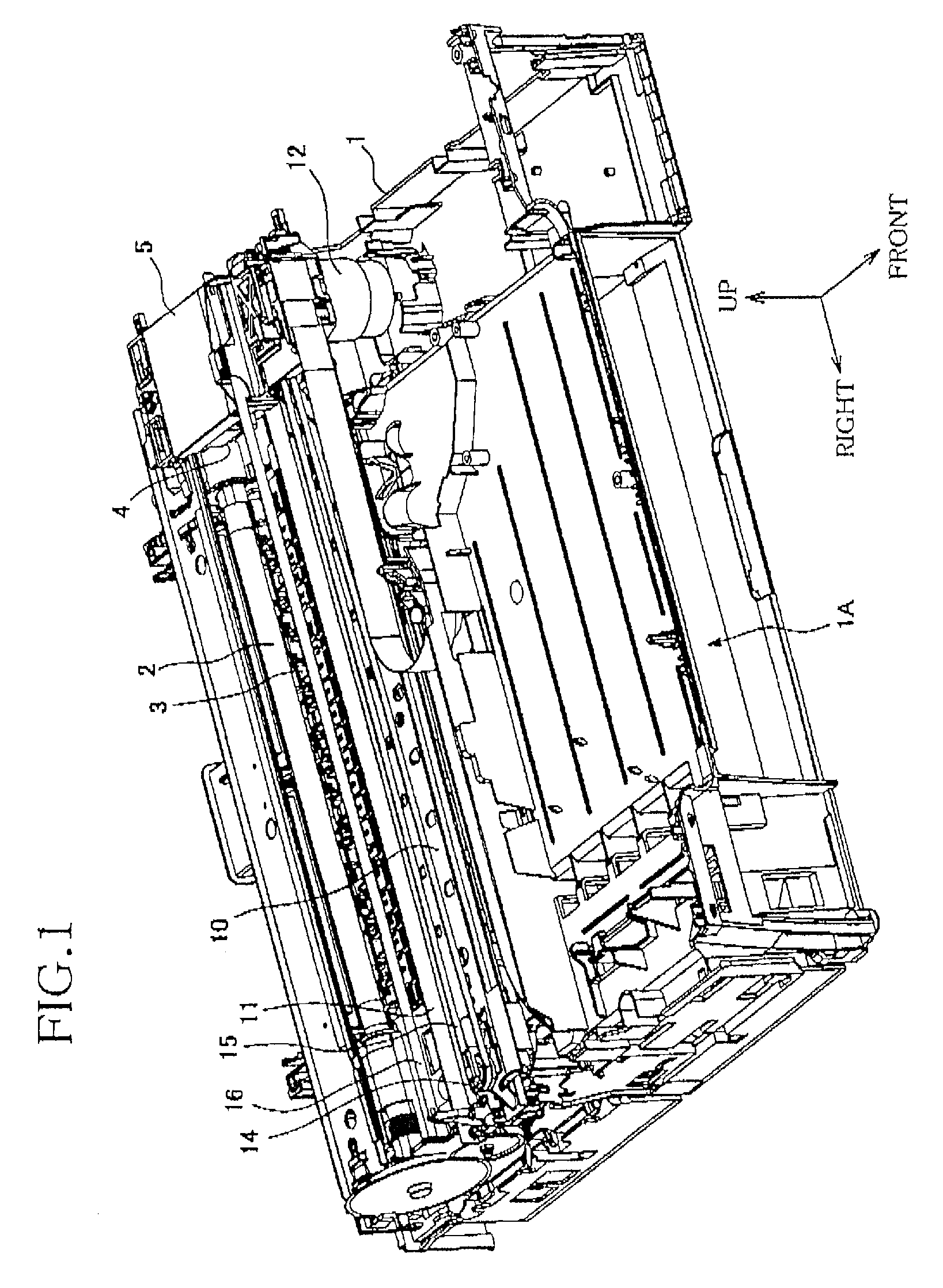
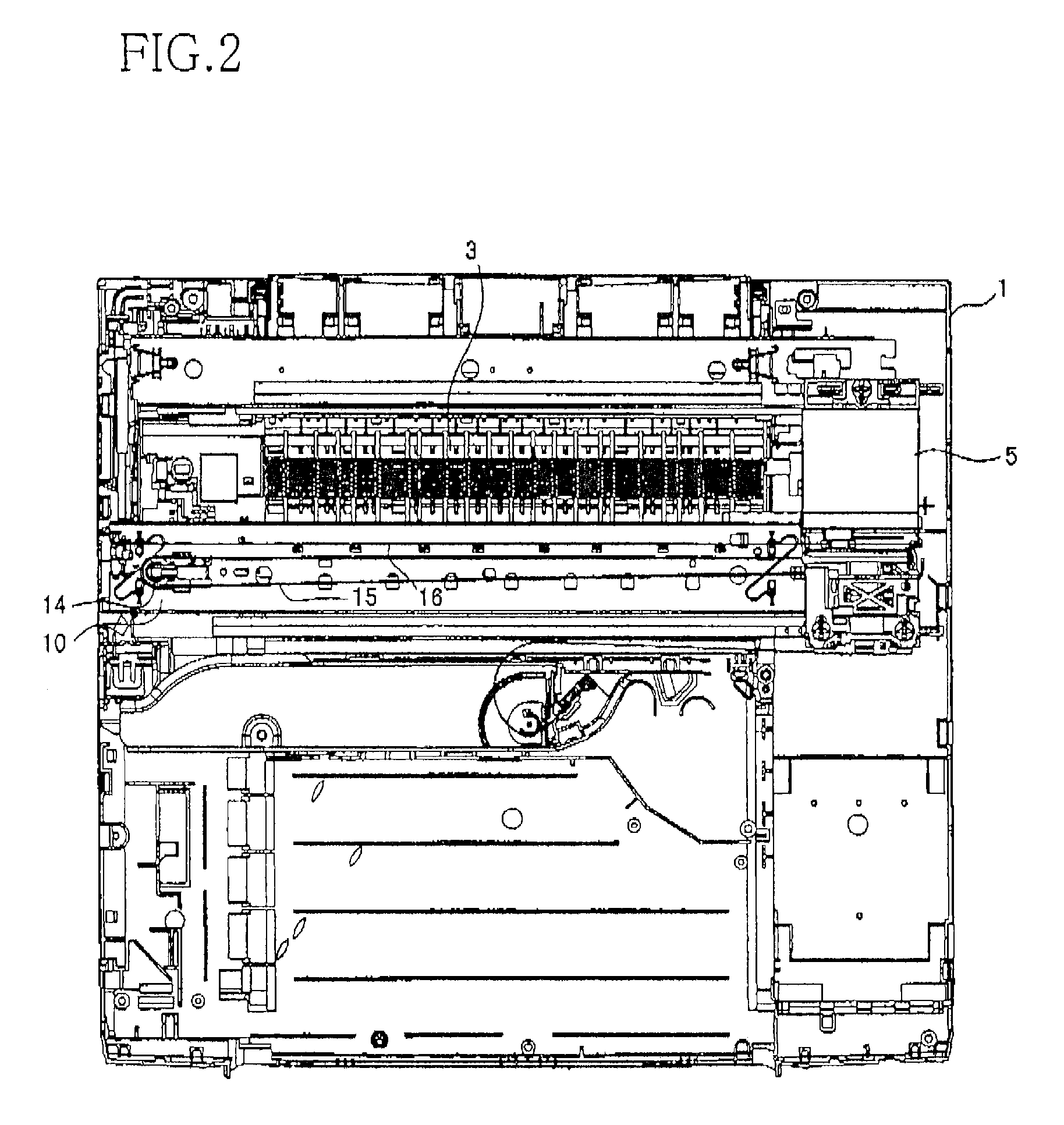
[0020]Hereinafter, there will be described preferred embodiments of the present invention with reference to the drawings. As shown in FIG. 1, a lower cover portion 1 of an inkjet printer as an embodiment to which the present invention is applied includes an opening portion 1A that is provided in a lower portion thereof. A sheet tray (not shown) is insertable into or retractable from the opening portion 1A. A recording sheet (not shown) as a recording medium that is accommodated in the sheet tray is conveyed onto a platen 3 through various sorts of rollers including a feeding roller 2. In the following description of each of the components, a direction extending from the feeding roller 2 to the platen 3 will be referred to as a frontward, and a portion, an end, or a side of the each component which is located nearer to the platen 3 relative to the paper feeding roller 2 will be referred to as a front portion, a front end, or a front side of the each component. Also, a portion, an end...


PUM


Abstract

A printer includes: a recording head which records an image on a recording medium; a carriage which carries the recording head and is movable in a scanning direction; a guide member which extends in the scanning direction and guides a movement of the carriage in the scanning direction; an angle-controlling member which is supported by the carriage to be pivotable relative thereto and controls an angular position of the carriage relative to the guide member in a state in which at least one contact surface of the angle-controlling member is in contact with a surface of the guide member that extends in the scanning direction; and a pivotal-position adjusting device which adjusts a pivotal position of the angle-controlling member relative to the carriage.

Description

CROSS REFERENCE TO RELATED APPLICATION[0001]The present application claims priority from Japanese Patent Application No. 2007-140534, which was filed on May 28, 2007, the disclosure of which is herein incorporated by reference in its entirety.BACKGROUND OF THE INVENTION[0002]1. Field of the Invention[0003]The present invention relates to a printer including a recording head that records an image on a recording medium while moving in a scanning direction.[0004]2. Discussion of Related Art[0005]There is known an inkjet printer including: (a) a recording head which ejects droplets of ink toward a recording medium; (b) a carriage which carries the recording head and is movable in a scanning direction; (c) a guide member which extends in the scanning direction and guides a movement of the carriage in the scanning direction. In the inkjet printer, the carriage moves in the scanning direction, guided by the guide member, and the recording head carried by the carriage ejects the droplets of...

Claims


Application Information

Patent Timeline
Patent Type & Authority Patents(United States)
IPC IPC(8): B41J2/165
CPCB41J25/304
Inventor KURIKI, KUMIKOSUGIURA, TOSHIO
Owner BROTHER KOGYO KK
Why Eureka
Try Eureka