
Lens system for digital camera

a digital camera and lens system technology, applied in the field of lenses, can solve the problems of increased manufacturing cost, large number of lens elements, heavy weight, etc., and achieve the effect of reducing the cost of assembling and mounting the lens elements, increasing the manufacturing cost, and increasing the manufacturing cos

Active Publication Date: 2006-12-14
HON HAI PRECISION IND CO LTD
View PDF7 Cites 4 Cited by
  • Summary
  • Abstract
  • Description
  • Claims
  • Application Information

AI Technical Summary

Benefits of technology

The patent describes a lens system for a digital camera that includes three lens elements. The first lens element is made of glass and has two aspheric surfaces. The second lens element is made of optical plastic and has two aspheric surfaces. The third lens element is made of glass and has one aspheric surface. The lens system has a unique design that provides improved image quality and reduced aberration. The technical effects of this lens system include improved image quality, reduced aberration, and improved optical performance.

Problems solved by technology

Lenses having a large number of lens elements tend to be large, heavy, and expensive to manufacture.
This greater manufacturing cost is caused by the added cost of assembling and mounting the lens elements into a lens barrel as well as the materials used in their construction.
However, the optical properties of most plastic lens elements are highly sensitive to changes in temperature and humidity, such as when the digital camera is used outdoors on very hot or cold days.
On top of this, the hardness of optical plastic material is lower than that of an optical glass material, so the surfaces of such lens elements are easily scraped or abraded, which can also affect image precision.
However, glass aspheric lenses cannot be easily produced by traditional glass grinding and polishing techniques.
In addition, glass lens elements are heavier than plastic lens elements and thus defeats the goal of producing more light-weight digital cameras.
Although the typical lens may satisfy the requirements for imaging, the resolution of the lens is low and may affect the image performance.

Method used


Image

  • Lens system for digital camera
  • Lens system for digital camera
  • Lens system for digital camera

Examples


Embodiment Construction

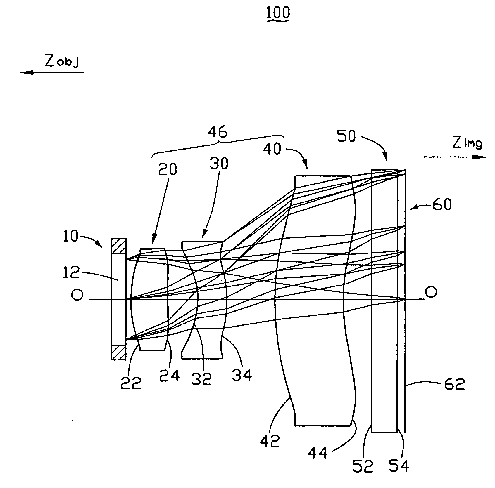
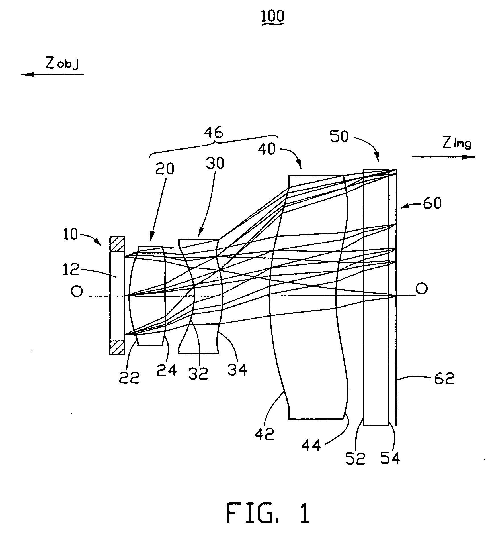
[0017] Referring to FIG. 1, an optical module 100 of a digital camera of a preferred embodiment includes an aperture stop 10, a first lens element 20, a second lens element 30, a third lens element 40, an optical board 50, and an imaging sensor 60, which are arranged in that order from an object side designated as “Zobj” to an image side designated as “Zimg”. The first lens element 20, the second lens element 30, and the third lens element 40 together may be considered, as a group, to constitute a lens system 46 of the optical module 100. Line OO represents an optical axis of the lens system.

[0018] The aperture stop 10 includes a stop plane 12, which faces the first lens element 20. The aperture stop 10 is the first component to receive light rays when the optical module 100 is used. Therefore, the light rays can easily be controlled using the aperture stop 10.

[0019] The first lens element 20 is biconvex and aspheric. The first lens element 20 includes a first aspheric surface 22 ...


PUM


Abstract

A lens system (46) for a digital camera consecutively includes a first lens element (20), a second lens element (30), and a third lens element (40). The first lens element is biconvex and has a first aspheric surface (22) and an opposite second aspheric surface (24). The second lens element is concavo-convex and includes a third aspheric surface (32) and an opposite fourth aspheric surface (34). The third lens element convexo-concave and has a fifth aspheric surface (42) and an opposite sixth aspheric surface (44). The first lens element is made of glass, and the second lens element and the third lens are made of optical plastic.

Description

BACKGROUND OF THE INVENTION [0001] 1. Field of the Invention [0002] The present invention generally relates to a lens systems for devices such as digital cameras and, more particularly, to a lens system that has optical elements with aspheric surfaces. [0003] 2. Discussion of the Related Art [0004] Digital cameras utilizing high-resolution electronic imaging sensors typically require high-resolution optical elements such as lenses. In addition, the lenses generally must be very compact, so that they can be incorporated into devices such as palm-sized computers, cellular telephones, and the like. [0005] Lenses for digital cameras generally have a plurality of individual lens elements. The lens elements are typically spherical and so usually create spherical aberration. Chromatic aberration, coma aberration, distortion, and field curvature are also common optical aberrations that occur in the imaging process of a typical lens. A large number of lens elements are generally required in ...

Claims


Application Information

Patent Timeline
Patent Type & Authority Applications(United States)
IPC IPC(8): G02B9/12
CPCG02B9/12G02B13/18G02B13/16G02B13/0035
Inventor SUN, WEN-HSIN
Owner HON HAI PRECISION IND CO LTD
Learn More