Active-load dominant circuit for common-mode glitch interference cancellation

a technology of active load and interference cancellation, applied in the field of pulse filters, can solve problems such as voltage dropt, latch b>103/b> malfunction, power consumption, etc., and achieve the effect of minimizing power consumption and die area

Active Publication Date: 2010-05-20
WUXI WENXIN ELECTRONICS TECH CO LTD
View PDF5 Cites 3 Cited by
  • Summary
  • Abstract
  • Description
  • Claims
  • Application Information

AI Technical Summary

Benefits of technology

[0011]In view of the description above, an objective of the present invention is to provide an effective and robust means of glitch interference cancellation of a half-bridge or full-bridge high-side driver.
[0012]A still another objective of the present invention is to further provide a novel active-load dominant circuit capable of generating a large voltage swing for driving a latch so that the latch can be easily implemented to operate normally.
[0016]The present novel means of glitch interference cancellation, with a pair of proposed active-load dominant networks and a pair of pull-up networks, can be utilized to provide a large voltage swing of at least one set signal and at least one reset signal to accomplish a common-mode glitch interference cancellation. The present novel invention can greatly reduce the common-mode glitch interferer around the power lines, reduce the die area, and consume no dc power.
[0019]The large voltage swing of the present invention is due to the design that each of the set signal and the reset signal is supplied from the supply voltage potential through the pull-up network, or pulled down to the reference ground through the active-load network. No dc conducting path exists in each of set and reset conditions. Since the set and reset signals can be assigned without dc current, the resistors in the pull-down network can then be omitted and both the power consumption and the die area can be minimized.
[0020]To make it easier for our examiner to understand the objective of the invention, its structure, innovative features, and performance, we use a preferred embodiment together with the attached drawings for the detailed description of the invention.

Problems solved by technology

As a result, the certain period the capacitor takes to reach a stable state causes a glitch period.
This may also cause the latch 103 malfunction.
As a result, the issues of voltage dropt, power consumption, and die area of a pulse filter are then tangled in the design process.

Method used


Image

  • Active-load dominant circuit for common-mode glitch interference cancellation
  • Active-load dominant circuit for common-mode glitch interference cancellation
  • Active-load dominant circuit for common-mode glitch interference cancellation

Examples


Embodiment Construction

[0033]The present invention will be described in more detail hereinafter with reference to the accompanying drawings that show the preferred embodiments of the invention.

[0034]As is mentioned in the description of the related art, the pulled-down networks constructed with resistors will definitely consume dc power in building up a set signal level or a reset signal level. However, according to the CMOS logic, the output level is pulled up to the supply voltage or pulled down to the ground and consumes no dc power. Besides, if the latch doesn't take response during the glitch period, then the fault actions of the latch can then be avoided. The present invention grasps these points and offers a variety of solutions which will be disclosed in the following description.

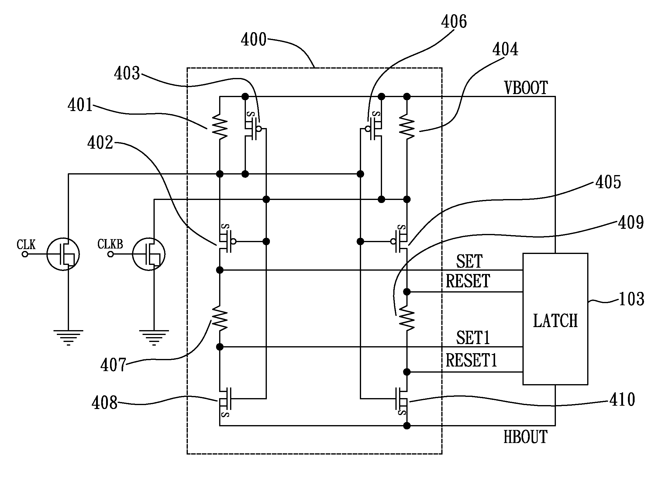
[0035]Please refer to FIG. 3, which shows a circuit diagram of a preferred embodiment of the present invention for common-mode glitch interference cancellation. As shown in the FIG. 3, the pulse filter 400 includes a resi...


PUM


Abstract

“An active-load dominant circuit for common-mode glitch interference cancellation, biased between a first voltage potential and a second voltage potential with an accompanying common-mode glitch interferer. The active-load dominant circuit includes a pair of pull-up networks and a pair of active-load networks. The common-mode glitch interferer is cancelled out due to a symmetric structure of the pair of pull-up networks. At least one set signal and at least one reset signal are provided to a latch in response to a clock signal or a complemented clock signal. At least one of the set signal and the reset signal can be pulled up to the first voltage potential or pulled down to the second voltage potential. The voltage difference of the set signal and the reset signal is large enough for a latch.”

Description

BACKGROUND OF THE INVENTION[0001]1. Field of the Invention[0002]The present invention relates to a pulse filter, and more particularly to a pulse filter capable of performing common-mode glitch interference cancellation in a half-bridge or full-bridge high-side driver.[0003]2. Description of the Related Art[0004]To describe the related art of the present invention, the relation between a pulse filter and a half-bridge or full-bridge high-side driver shall be introduced first. Please refer to FIG. 1, which shows the architecture of a typical half-bridge driver 100. As shown in FIG. 1, the typical half-bridge driver 100 at least includes a pulse generator 101, a pulse filter 102, and a latch 103.[0005]The pulse generator 101 is used for generating a clock (CLK) signal and a complemented clock (CLKB) signal. The pulse filter 102 is used for cancelling a common-mode glitch interference accompanying the power lines of VBOOT and HBOUT, and generating a set signal and a reset signal to the...

Claims


Application Information

Patent Timeline
Patent Type & Authority Applications(United States)
IPC IPC(8): H03K3/35H03K3/289
CPCH03K17/162H03K5/1252
Inventor WANG, YEN-PINGWANG, YEN-HUICHEN, PEI-YUAN
Owner WUXI WENXIN ELECTRONICS TECH CO LTD
Why Eureka
Try Eureka