

Focus Control Device and Focus Control Method
a technology of focus control and control device, which is applied in the direction of color television details, instruments, television systems, etc., can solve the problems inability to achieve focus, so as to achieve the effect of shortened driving time of focus lens
- Summary
- Abstract
- Description
- Claims
- Application Information
AI Technical Summary
Benefits of technology
Problems solved by technology
Method used
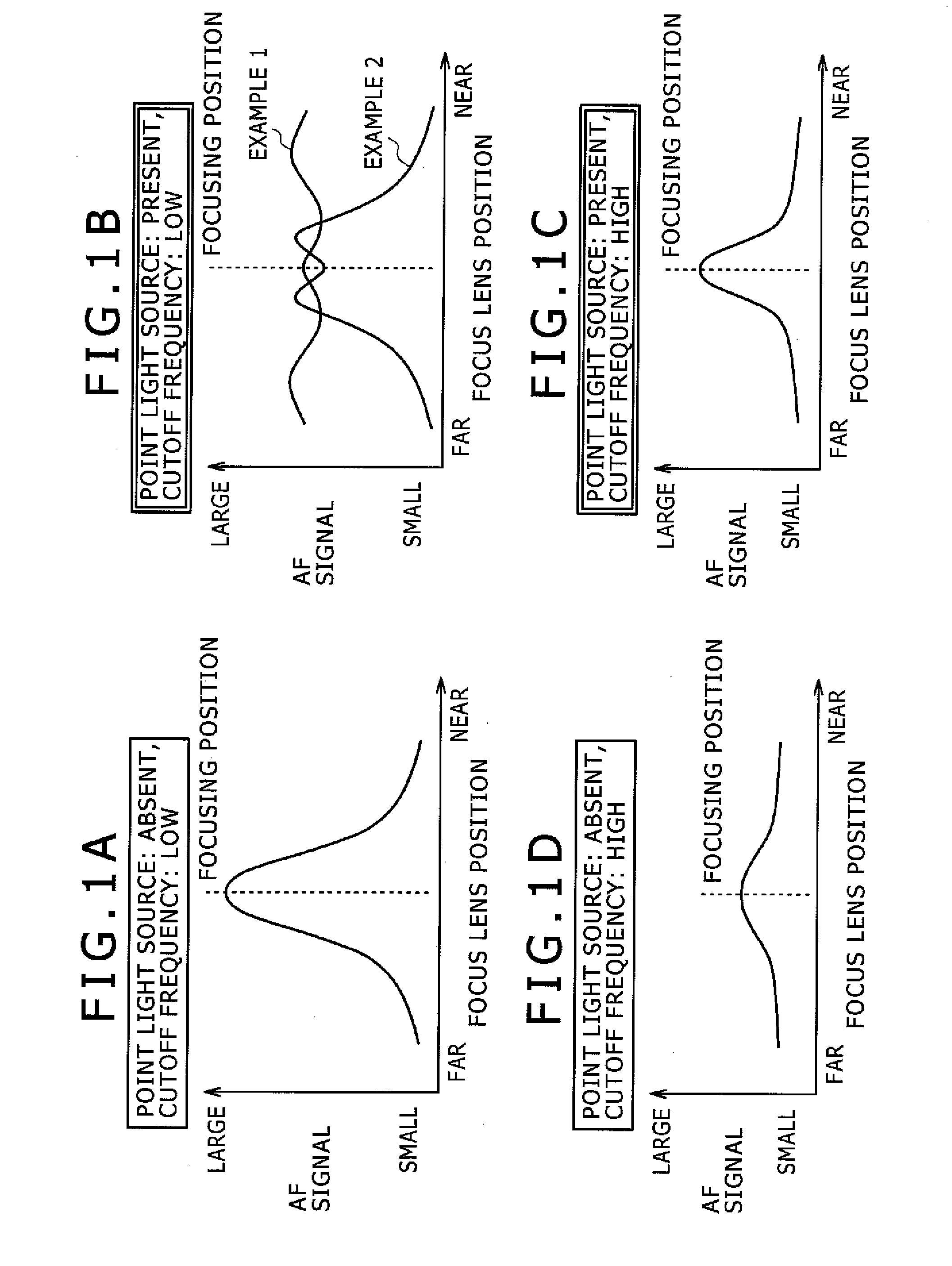
Image

Examples
Embodiment Construction
[0033]Hereafter, description will be given to an embodiment of the invention based on an example in which the invention is applied to a monitoring camera for prevention of crimes.
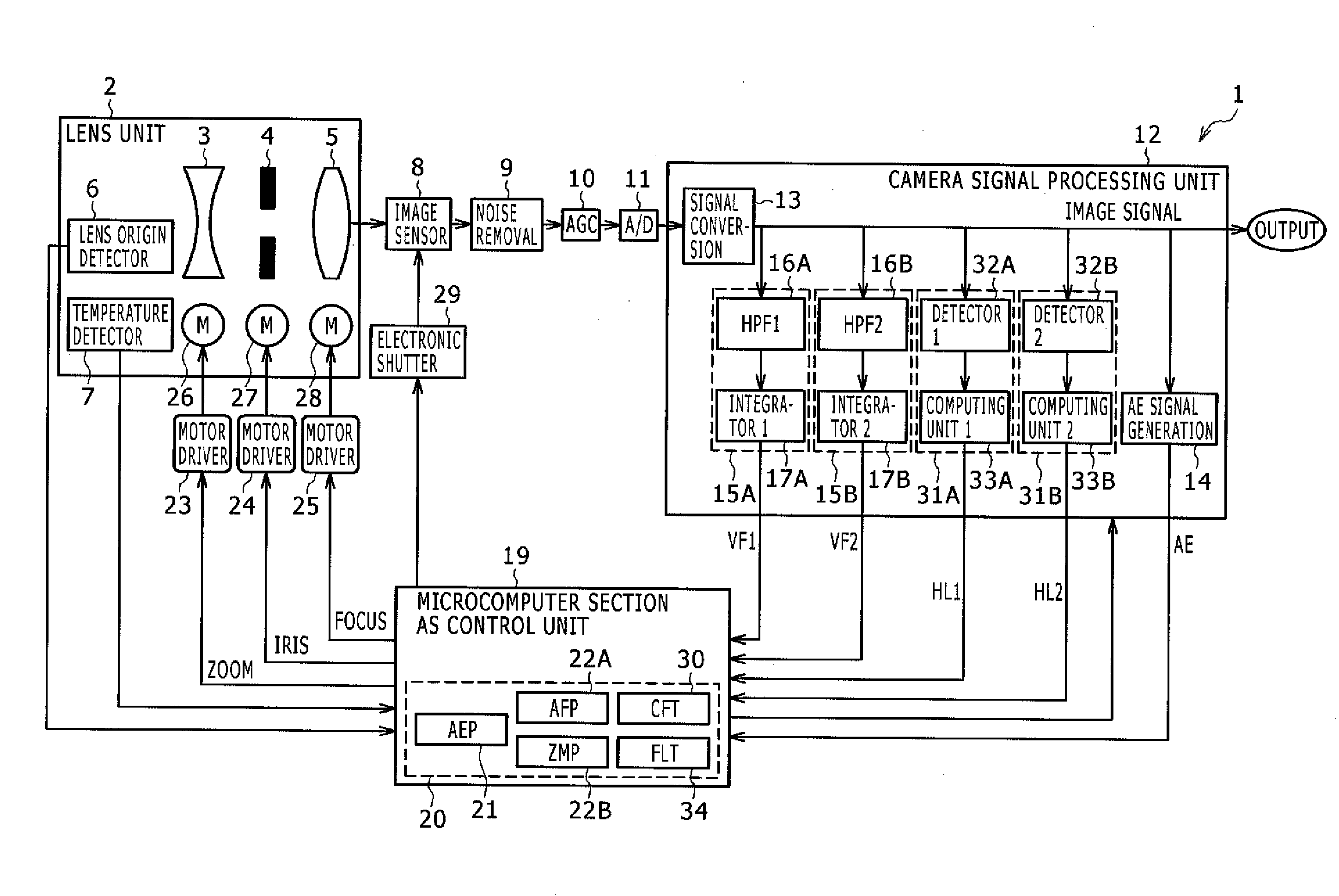
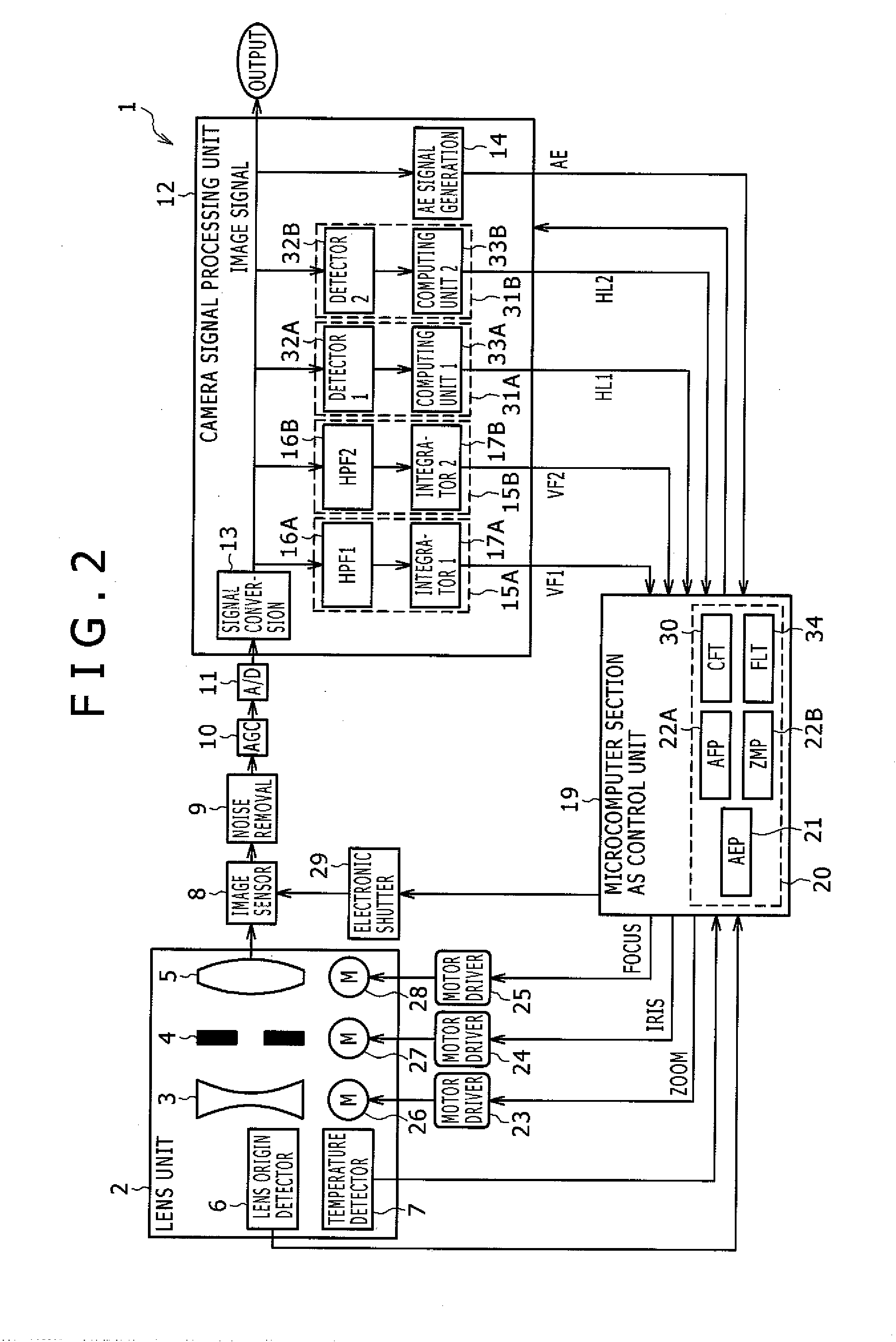
[0034]FIG. 2 is a block diagram illustrating the overall configuration of an image pickup device 1 in the embodiment of the invention. Description will be given to the operation of the entire device based on this block diagram.
[0035]In the image pickup device 1, a lens unit 2 includes: a zoom lens group 3 that variably magnifies light flux from a subject; an iris mechanism 4 for adjusting the amount of light received; and a focus lens group 5 that carries out focus adjustment. An optical image of the subject is formed on the light receiving surface of an image sensor 8.
[0036]In addition, the lens unit 2 is provided with a lens origin detector 6 comprised of, for example, a photointerruptor and the like and a temperature detector 7 comprised of a diode and the like. The lens origin detector 6 detects the len...
PUM
 Abstract
Description
Claims
Application Information