Lighting Device and Projector

a technology of projector and light source, which is applied in the direction of lighting and heating equipment, instruments, optical elements, etc., can solve the problems of uniform overall illumination, and achieve the effect of reducing size, uniform illumination, and high efficiency

Active Publication Date: 2010-05-20
SEIKO EPSON CORP
View PDF21 Cites 6 Cited by
  • Summary
  • Abstract
  • Description
  • Claims
  • Application Information

AI Technical Summary

Benefits of technology

[0012]It is an advantage of some aspects of the invention to provide a lighting device which is compact and capable of achieving preferable light utilization efficiency and providing uniform illuminance on a light receiving area. It is another advantage of some aspects of the invention to provide a projector which is compact and capable of producing high-quality images.

Problems solved by technology

When the peripheral area having lowered illuminance is used for illumination, the overall illuminance does not become uniform.

Method used


Image

  • Lighting Device and Projector
  • Lighting Device and Projector
  • Lighting Device and Projector

Examples


first embodiment

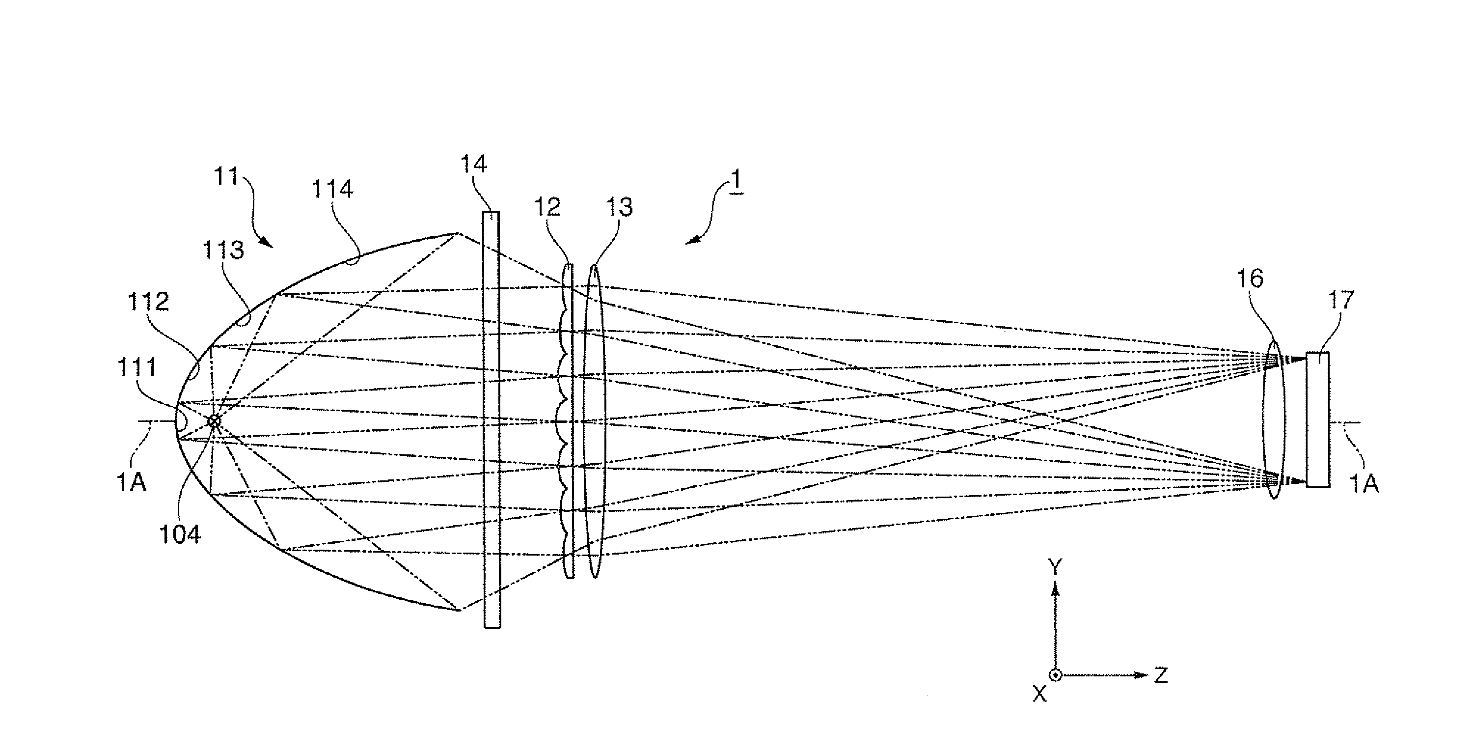
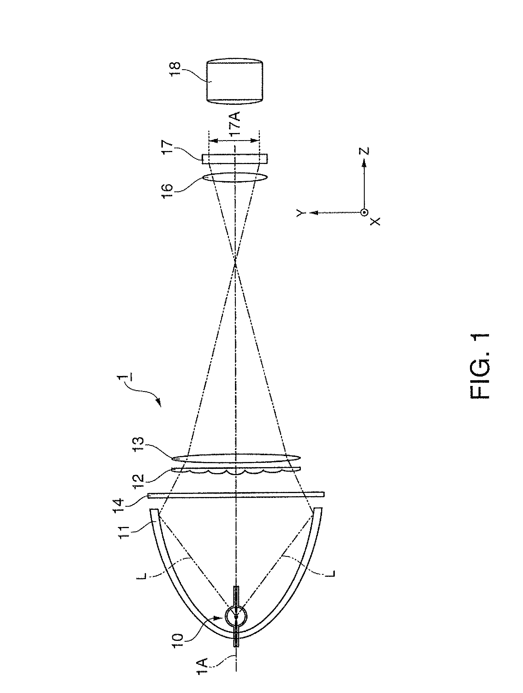
[0047]FIG. 1 schematically illustrates a general structure of a lighting device 1 according to a first embodiment.

[0048]As illustrated in FIG. 1, the lighting device 1 includes a light emission lamp (light source) 10, a reflector 11, a lens array 12, and a condenser lens (stacking system) 13. Light L emitted from the light emission lamp 10 is reflected by the reflector 11, and travels substantially in the direction along a main optical axis 1A. Then, the light L passes through the lens array 12 and the condenser lens 13, and illuminates a light receiving area 17A. The main optical axis 1A is a center axis of lights emitted from the light source lamp 10 and reflected by the reflector 11. The center of gravity of the intensity distribution on the cross section orthogonal to the main optical axis 1A of the lights almost coincides with the cross point of the cross section and the main optical axis 1A. Each of the light emission lamp 10 and the reflector 11 in this embodiment has a shape...

second embodiment

[0081]A lighting device according to a second embodiment of the invention is hereinafter described. The second embodiment is different from the first embodiment in that a plurality of reflection surfaces are not disposed adjacent to one another but are disposed with connection surfaces interposed between the respective reflection surfaces, and that lens portions are disposed such that the crossing portion of the lens array and the light source axis does not agree with the center of the lens portions.

[0082]FIG. 6A schematically illustrates a general structure of a lighting device 2 according to the second embodiment, and FIG. 6B illustrates the positional relationship between the respective elements shown in FIG. 6A. The lighting device 2 includes a lamp light source similar to that of the first embodiment, but FIG. 6A shows only a light emission point 204 in place of the detailed structure of the lamp light source.

[0083]As illustrated in FIG. 6A, a reflection surface 211, a connecti...

third embodiment

[0097]A lighting device according to a third embodiment of the invention is now described. The third embodiment is different from the first embodiment in that a polarization conversion element is disposed between the lens array and the condenser lens. The polarization conversion element equalizes polarization condition of entering light and outputs the equalized light.

[0098]FIG. 7 schematically illustrates a general structure of a lighting device 3 according to the third embodiment.

[0099]As illustrated in FIG. 7, the lighting device 3 includes a light emission lamp 30, a reflector 31, a lens array 32, a polarization conversion element 35, and a condenser lens 33. A filter 34 is disposed between the reflector 31 and the lens array 32. The lighting device illuminates a light receiving area 37A of a liquid crystal light valve 37. A field lens 36 is provided between the light receiving area 37A and the condenser lens 33. Light having entered the light receiving area 37A is converted int...


PUM


Abstract

A lighting device includes: a light source which emits light around a light source axis; a reflector which has a plurality of reflection surfaces for reflecting light emitted from the light source; a plurality of converging units each of which is provided for the corresponding reflection surface of the plural reflection surfaces to receive light released from the corresponding reflection surface; and a stacking system which stacks light having passed the plural converging units on a light receiving area wherein each of the plural reflection surfaces is formed by a part of a spheroid having focuses at the position of the corresponding converging unit and the position of the light source, and each focal distance of the plural converging units becomes longer as the distance between the position of the converging unit and the light source axis increases.

Description

BACKGROUND[0001]1. Technical Field[0002]The present invention relates to a lighting device and a projector.[0003]2. Related Art[0004]A projector is known as an apparatus displaying large-screen images. This projector includes a lighting device, an image forming device, a projection lens, and other units. Illumination light emitted from the lighting device is converted into image light representing images by the image forming device. This image light is expanded and projected by the projection lens such that large-screen images can be obtained more easily than a direct-viewing type image display apparatus.[0005]For improving image quality of the projector, it is extremely important to equalize illuminance throughout a light receiving area of the image forming device illuminated by the lighting device. A fly-eye lens array is known as an illuminance equalizing element for equalizing illuminance of a lighting device including a lamp light source. A typical fly-eye lens array has a plur...

Claims


Application Information

Patent Timeline
Patent Type & Authority Applications(United States)
IPC IPC(8): G03B21/28F21V13/04F21V13/14F21Y101/00
CPCG03B21/2026G03B33/12G03B21/208G03B21/2073
Inventor SAKATA, HIDEFUMI
Owner SEIKO EPSON CORP
Why Eureka
Try Eureka