Lighting system and lighting method of highway tunnel

A technology for road tunnels and lighting systems, applied in the field of road and bridge engineering, can solve the problems of high power consumption, high cost of solar cells, unsatisfactory use effects, etc., and achieve the effect of saving power and uniform lighting

Active Publication Date: 2013-06-26
深圳市深大南方实业发展有限公司
View PDF7 Cites 16 Cited by
  • Summary
  • Abstract
  • Description
  • Claims
  • Application Information

AI Technical Summary

Problems solved by technology

However, its defect is that the lighting fixtures at the tunnel entrance need to be adjusted to a level very close to the natural light. In sunny days when the natural light is relatively high, the artificial light at the tunnel entrance and inside the tunnel needs to be adjusted to a higher level. This undoubtedly requires It consumes a lot of power, even if the solar battery is used as an auxiliary power supply, it is actually difficult to meet the electricity demand, and the cost of the solar battery is also high, and the use effect is not ideal

Method used


Image

  • Lighting system and lighting method of highway tunnel
  • Lighting system and lighting method of highway tunnel
  • Lighting system and lighting method of highway tunnel

Examples


Embodiment 1

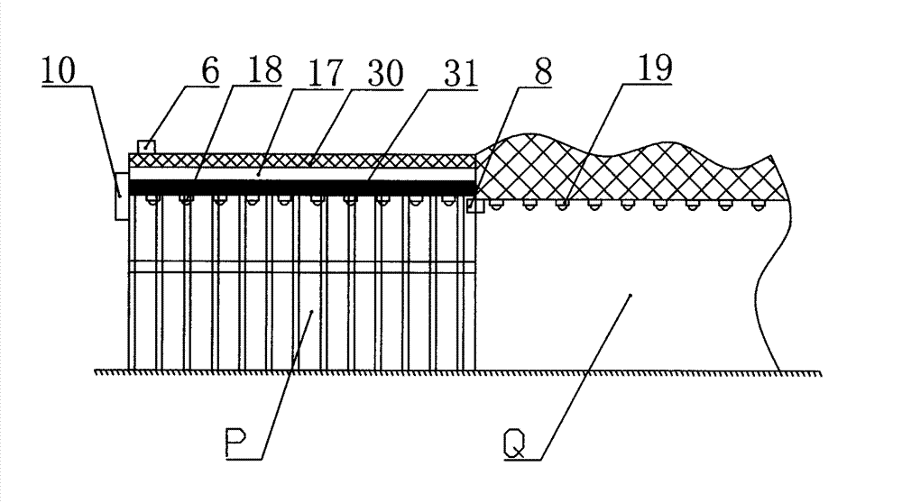
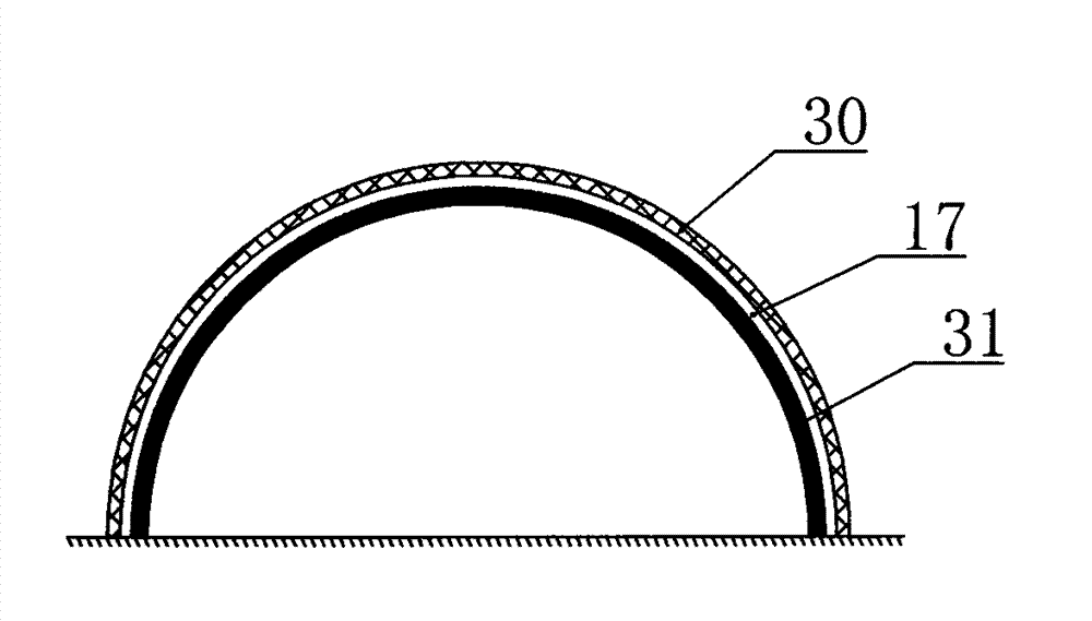
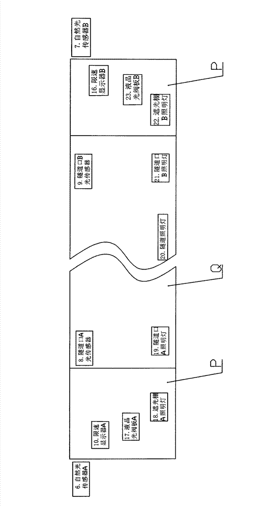
[0027] according to figure 1 with Figure 4 As shown, a road tunnel lighting system described in this embodiment includes a tunnel lighting lamp 20 arranged in the middle of the tunnel Q, a tunnel entrance lighting lamp installed at the two ports of the tunnel Q, and a tunnel lighting lamp installed in the tunnel Q The shade P outside the two ports, the shade P includes a support frame 31 and an outer cover plate 30 fixed on the support frame 31, the inner side of the outer cover plate 30 is provided with a liquid crystal light valve plate 17, and the liquid crystal light valve plate 17 is arranged along the The length direction of P is distributed, and there are also shade lighting lights inside the shade shed P; natural light sensors are respectively arranged outside the two shade sheds P, and tunnel mouth light sensors are respectively installed at the junction of the tunnel Q port and the two shade sheds P; The liquid crystal light valve plate, the shade lighting lamp, th...

Embodiment 2

[0043] The difference between this embodiment and Embodiment 1 is that a liquid crystal light valve plate is arranged on the outer cover plate 30 at the top of the sunshade P, and the outer cover plate 30 provided with the liquid crystal light valve plate is a transparent cover plate, and the outer cover plates of the rest are 30 is a non-transparent cover plate. With this structure, the number of liquid crystal light valve plates can be reduced, which is more energy-saving, and is suitable for tunnels with a small difference in illuminance between inside and outside the tunnel.

[0044] In addition, vehicle speed measuring devices can be installed outside the awnings on both sides of the tunnel. The vehicle speed measuring devices on both sides can cooperate to determine whether there are vehicles passing through the tunnel. If there are vehicles passing, the predetermined lighting plan will be executed. If there are no vehicles passing, the lights can be turned off. Reduce l...


PUM


Abstract

The invention discloses a lighting system and a lighting method of a highway tunnel. The lighting system comprises tunnel lighting lamps arranged on the middle part of the interior of the tunnel, tunnel portal lighting lamps arranged on two port parts of the interior of the tunnel, and light shielding sheds arranged on the exterior of two ports of the tunnel, wherein the inner side of the light shielding shed is provided with a liquid crystal light valve plate and a light shielding shed lighting lamp, the lighting lamps in the light shielding sheds and the tunnel are matched with a control system to be controlled, so that the lighting change of a light transition section from the outer end of the light shielding shed to the interior of the tunnel port is more mitigatory, and the lighting intensity of the light shielding shed lighting lamps, the tunnel lighting lamps and the tunnel portal lighting lamps can be adjusted by the control system, so that the electrical energy can be saved on the premise that uniform and safe lighting is ensured.

Description

technical field [0001] The invention belongs to the technical field of road and bridge engineering, and in particular relates to a road tunnel lighting system. Background technique [0002] At present, the interior of the tunnel is generally illuminated by artificial light throughout the day, and the lighting requirements are different from those of ordinary roads. When entering a tunnel under artificial light from an ordinary road under natural light conditions, the sudden change in brightness will make it difficult for the driver's eyes to quickly adapt to the lighting environment inside the tunnel. When the car drives out of the tunnel to the ordinary road , The sudden change in brightness will also make it difficult for the driver's eye recognition ability to quickly adapt to the light environment of ordinary roads. General tunnel lighting is mainly composed of tunnel entrance lighting and tunnel interior lighting. Among them, the tunnel lighting at the tunnel entrance...

Claims


Application Information

Patent Timeline
Patent Type & Authority Applications(China)
IPC IPC(8): F21S8/00F21V1/14H05B37/02F21W131/101
Inventor 王军海
Owner 深圳市深大南方实业发展有限公司
Why Eureka
Try Eureka