Cooling system and method of controlling the same

a technology of cooling system and cooling chamber, which is applied in the direction of defrosting, refrigeration machines, domestic cooling apparatus, etc., can solve the problems of reducing the heat-exchange efficiency of air passing through the evaporator, forming on the surface, and frosting on the surface of the evaporator

Inactive Publication Date: 2010-05-27
SAMSUNG ELECTRONICS CO LTD
View PDF13 Cites 13 Cited by
  • Summary
  • Abstract
  • Description
  • Claims
  • Application Information

AI Technical Summary

Benefits of technology

[0036]The method may further include respectively comparing the amounts of frost in the sections with a reference amount; and performing the defrosting operation, when the amount of frost in at least one section of the sections is more than the reference amount.

Problems solved by technology

Since the surface temperature of the evaporator cooling the indoor space through the refrigerating cycle is lower than the temperature of air in the indoor space, moisture condensed from the air of a relatively higher temperature in the indoor space is stuck to the surface of the evaporator and thus frost is formed on the surface of the evaporator.
The frost formed on the surface of the evaporator is gradually thickened as time goes by, and then the heat-exchanging efficiency of air passing through the evaporator is lowered and causes excessive power consumption.
However, this defrosting operation is performed based on the operating time of the compressor regardless of the real amount of the front formed on the surface of the evaporator, and thus is limited in the effective removal of the frost formed on the surface of the evaporator.

Method used


Image

  • Cooling system and method of controlling the same
  • Cooling system and method of controlling the same
  • Cooling system and method of controlling the same

Examples


Embodiment Construction

[0046]Reference will now be made in detail to the embodiments of the present invention, an example of which is illustrated in the accompanying drawings, wherein like reference numerals refer to like elements throughout. The embodiments are described below to explain the present invention by referring to the annexed drawings.

[0047]In these embodiments, among cooling systems using a refrigerating cycle, a refrigerator will be exemplarily described.

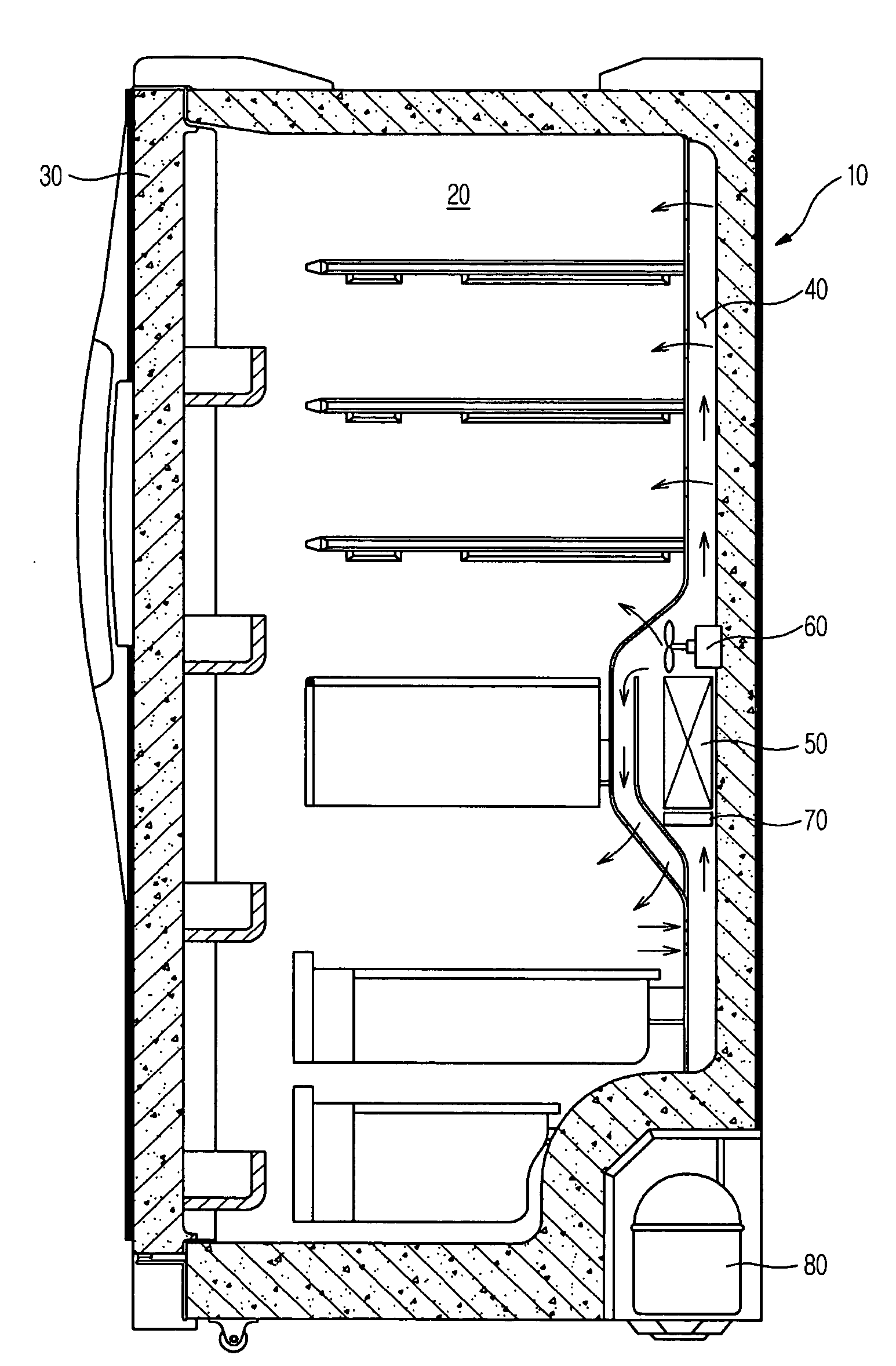
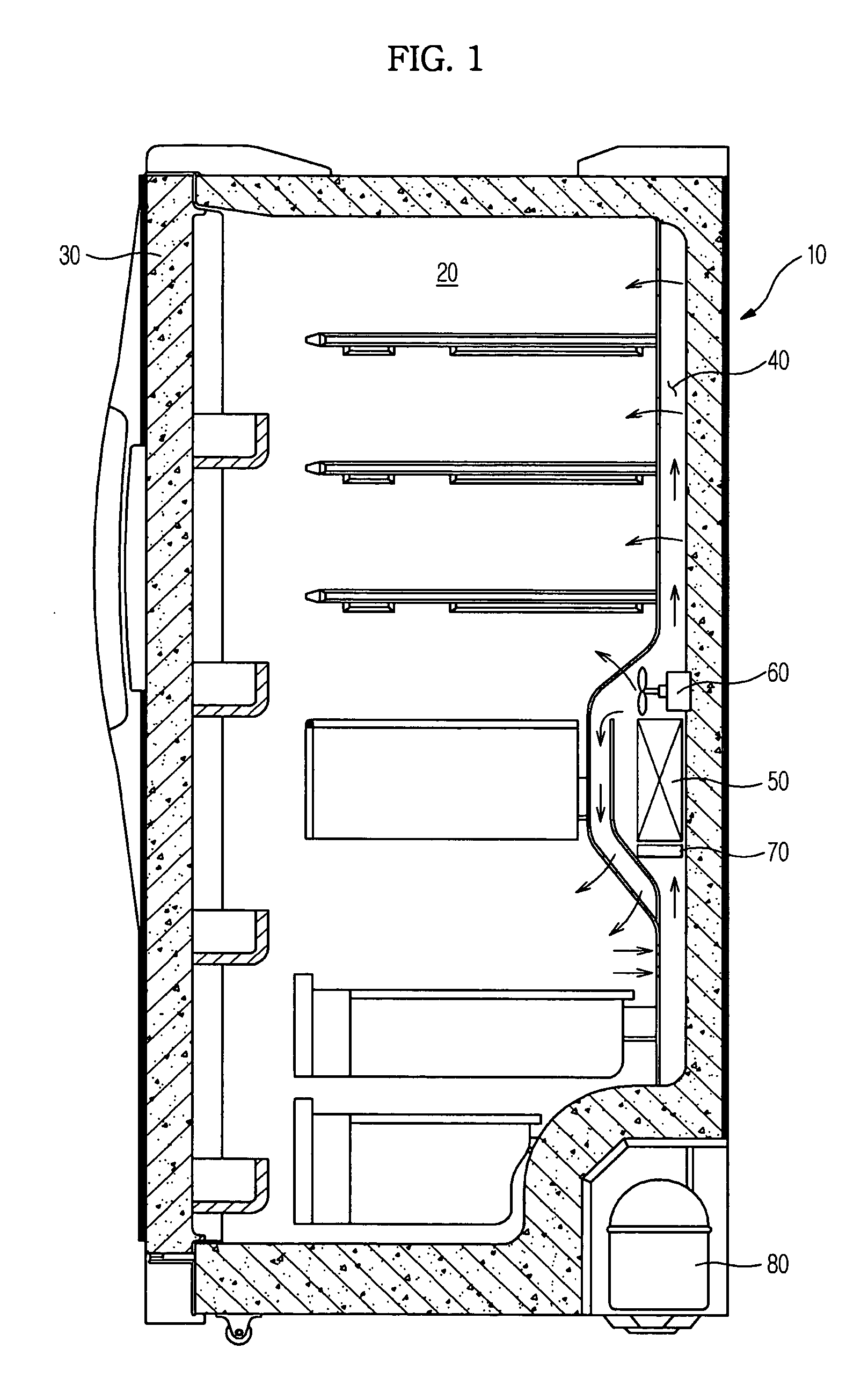
[0048]As shown in FIG. 1, the refrigerator includes a main body 10 provided with an opened front surface, and a storage chamber 20 provided in the main body 10 to store foods. The storage chamber 20 is horizontally divided into a freezing chamber and a cooling chamber side by side by an intermediate diaphragm. The front surfaces of the freezing chamber and the cooling chamber are opened, and doors 30 to shield the freezing chamber and the cooling chamber from the outside are respectively provided at the opened front surfaces of the freezing ...


PUM


Abstract

An oscillatory wave generating unit and an oscillatory wave sensing unit are installed at both ends of a refrigerant pipe of an evaporator of the cooling system, an amount of frost formed on the refrigerant pipe is determined by comparing a wave form of an oscillatory wave generated from one end of the refrigerant through the oscillatory wave generating unit and a wave form of the oscillatory wave sensed by the other one end of the refrigerant through the oscillatory wave sensing unit, and whether or not a defrosting operation is performed is determined by a result of the determination. The cooling system increases the accuracy in sensing the amount of the frost formed on the evaporator of a refrigerator, a Kimchi refrigerator, or an air conditioner, and respectively starts and ends the defrosting operation at proper points of time, thus enhancing a heat-exchanging performance and increasing energy efficiency.

Description

CROSS-REFERENCE TO RELATED APPLICATIONS[0001]This application claims the benefit of Korean Patent Application No. 2008-0117363, filed on Nov. 25, 2008, in the Korean Intellectual Property Office, the disclosure of which is incorporated herein by reference.BACKGROUND[0002]1. Field[0003]The present invention relates to a cooling system and a method of controlling the same, and more particularly to a cooling system, which senses frost formed on an evaporator by heat exchange, and a method of controlling the cooling system.[0004]2. Description of the Related Art[0005]In general, cooling systems are apparatuses, which circulate a refrigerant according to a refrigerating cycle and thus cool a designated space, and include a refrigerator, a Kimchi refrigerator, an air conditioner, etc.[0006]Here, the refrigerating cycle changes a refrigerant into four phases, such as compression, condensation, expansion, and evaporation, and thus needs to be provided with a compressor, a condenser, an expa...

Claims


Application Information

Patent Timeline
Patent Type & Authority Applications(United States)
IPC IPC(8): F25D21/02F25D21/06
CPCF25D21/02F25B2700/111F25D29/005
Inventor HAN, JEONG SULEE, SANG JUNSEO, KOOK JEONGYOON, HOKIM, JUNG HYEONCHOI, HYEN YOUNGRYU, O DO
Owner SAMSUNG ELECTRONICS CO LTD
Why Eureka
Try Eureka