Conveyor and deposition apparatus, and maintenance method thereof

Active Publication Date: 2010-05-27
ULVAC INC
View PDF11 Cites 312 Cited by
  • Summary
  • Abstract
  • Description
  • Claims
  • Application Information

AI Technical Summary

Benefits of technology

[0023]In this case, the upper frame can be moved to form a space above the lower frame, and also the constituent member of the deposition treatment passage that has been moved can be arranged in the space. Therefore, it is possible to bring the deposition treatment passage and the carrier transfer passage closer. Consequently, an advantage is obtained in that it is possible to make the installation area of the deposition apparatus small and narrow.
[0024]According to the present inv

Problems solved by technology

That is, as shown in FIG. 13, it is necessary to broaden an inner court 117, leading to a problem of an increased installation area required for the deposition apparatus

Method used


Image

  • Conveyor and deposition apparatus, and maintenance method thereof
  • Conveyor and deposition apparatus, and maintenance method thereof
  • Conveyor and deposition apparatus, and maintenance method thereof

Examples


Embodiment Construction

[0039]Next is a description of an embodiment of the present invention based on FIG. 1 to FIG. 12. In the drawings used for the following description, scales of respective members are appropriately modified for easy recognition of the respective members.

(Deposition Apparatus)

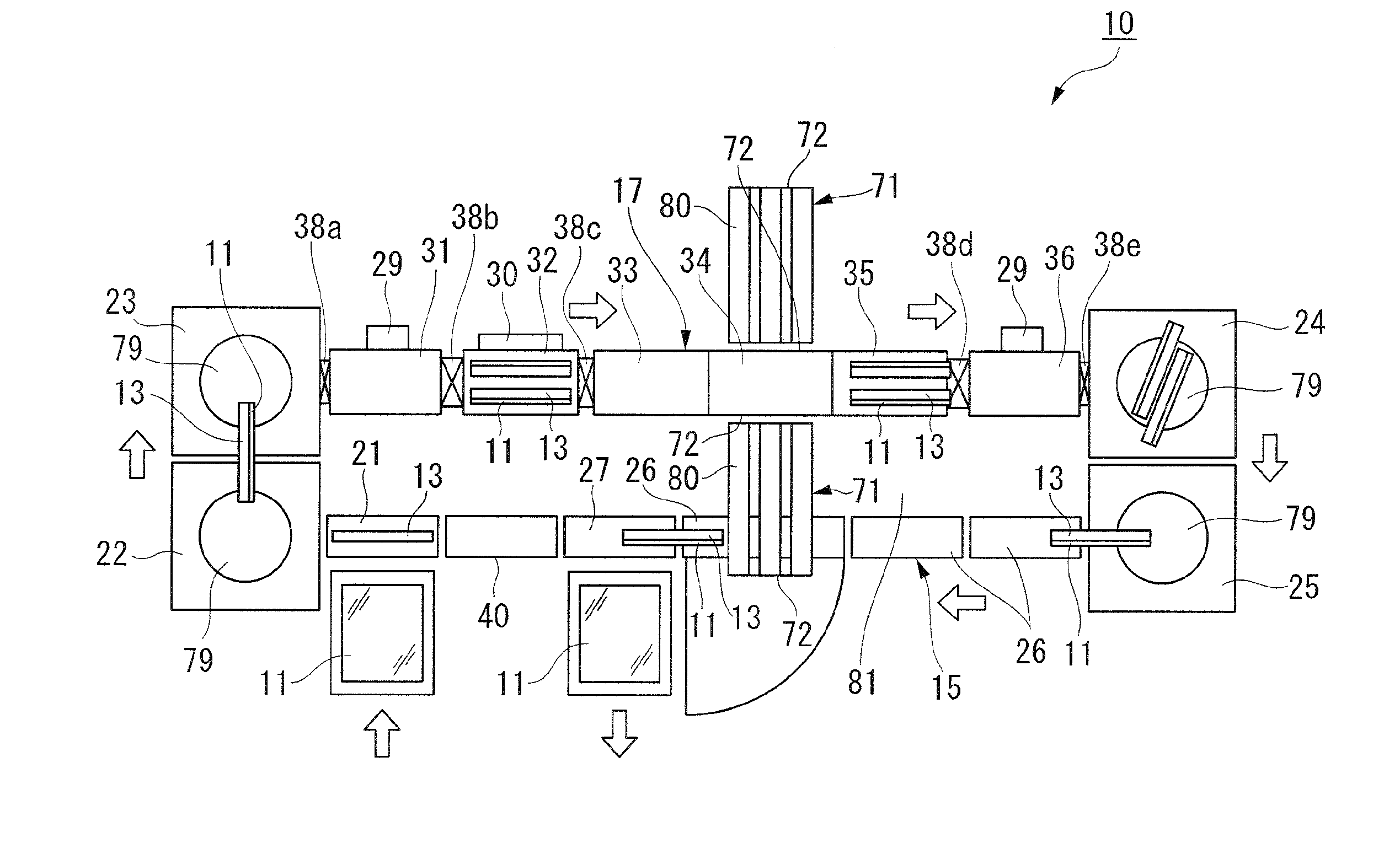
[0040]FIG. 1 is a planar view showing a general construction of a deposition apparatus.

[0041]As shown in FIG. 1, a deposition apparatus 10 in which carriers 13 for holding glass substrates 11 longitudinally are arranged for longitudinally includes a carrier transfer passage 15 which transfers the carriers 13 under an atmospheric pressure, and a deposition treatment passage 17 which performs deposition on the glass substrates 11 under a vacuum condition. Here, the deposition apparatus 10 is a deposition apparatus on the double-side deposition system with a constitution where the carriers 13 are allowed to be transferred two abreast through the deposition treatment passage 17 and where deposition is allowed from bo...


PUM


Abstract

A conveyor and a deposition apparatus, and a maintenance method thereof are disclosed. The conveyor includes a frame; a lower support mechanism for supporting a carrier on which is longitudinally mounted a substrate and for transferring the carrier; and an upper support mechanism for supporting the carrier, in which the frame comprises a lower frame and an upper frame, and in which the lower support mechanism is provided on the lower frame and the upper support mechanism is provided on the upper frame, the upper frame and the lower frame being configured to be separately movable. Therefore, with the rotational movement of the upper frame, it is possible to arrange a cathode member in a space formed above the lower frame. This can make the spacing between the deposition treatment passage and the carrier transfer passage small. As a result, it is possible to make an inner court of the deposition apparatus narrow. Therefore, in the conveyor capable of transferring a carrier and in the deposition apparatus including the conveyor and further including a vacuum treatment apparatus and a transfer system, it is possible to make the installation area thereof small and narrow.

Description

TECHNICAL FIELD[0001]The present invention relates to a conveyor and a deposition apparatus. Priority is claimed on Japanese Patent Application No. 2007-106877, filed on Apr. 16, 2007, the contents of which are incorporated herein by reference.BACKGROUND ART[0002]In the manufacturing process of liquid crystal displays and the like, a large-size glass substrate is subjected to a vacuum treatment such as a heating treatment and a deposition treatment. Therefore, a variety of vacuum treatment apparatuses have been developed. In one of them, a carrier-circulation-type in-line sputtering apparatus is used for depositing an ITO film (an electrode film) on the color filter side of the liquid crystal display (for example, see Patent Document 1).[0003]Sputtering apparatuses include a type of sputtering apparatus in which a glass substrate after sputtering is rotated or traversed in the vacuum and is then returned in the vacuum (a vacuum return type) and a type of sputtering apparatus in whic...

Claims


Application Information

Patent Timeline
IPC IPC(8): B05C13/00B65G21/00B23P11/00
CPCC23C14/50B65G49/062B65G49/068H01L21/67748B65G49/063C23C14/34H01L21/6719C23C14/56H01L21/67161H01L21/67751B65G49/061B65G2249/02Y10T29/49817H01L21/67236H01L21/67706H01L21/67712
Inventor ISHINO, KOJINAKAMURA, HAJIMEMATSUDA, MAYAKOSHINDOU, TAKAAKIKOSHIMIZU, TAKAHARU
Owner ULVAC INC
Why Eureka
Try Eureka