Eureka AIR delivers breakthrough ideas for toughest innovation challenges, trusted by R&D personnel around the world.

Wire holding mechanism, image forming apparatus and method of maintaining a wire

Inactive Publication Date: 2010-06-03
KYOCERA DOCUMENT SOLUTIONS INC
View PDF6 Cites 0 Cited by
  • Summary
  • Abstract
  • Description
  • Claims
  • Application Information

AI Technical Summary

Benefits of technology

[0009]The present invention provides a wire holding mechanism including a holding member that restricts movement of the wire when the holding member is attached to a predetermined member, and that can be attached to the predetermined member without using a fastening member.

Problems solved by technology

Thus, problems may arise in that a predetermined operation has to be performed so as to attach the clamp, and in that the electric wire may not be properly held by the clamp because the side of the clamp that is not fixed by a screw may be lifted up.

Method used


Image

  • Wire holding mechanism, image forming apparatus and method of maintaining a wire
  • Wire holding mechanism, image forming apparatus and method of maintaining a wire
  • Wire holding mechanism, image forming apparatus and method of maintaining a wire

Examples


Embodiment Construction

[0030]Hereinafter, embodiments of the present invention are described with reference to the drawings.

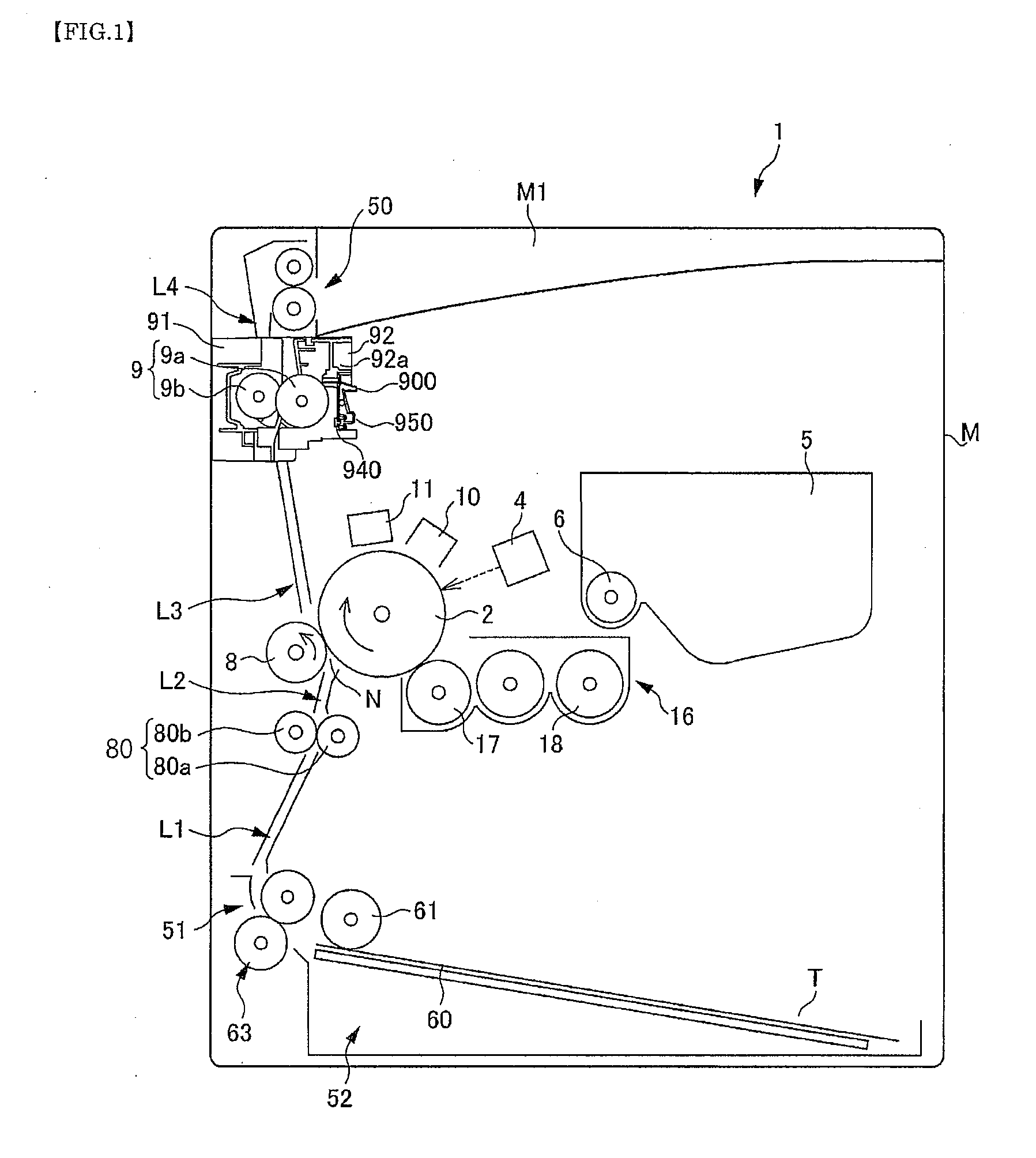
[0031]Referring to FIG. 1, the overall structure of a printer 1, which is an image forming apparatus according to an embodiment of the present invention, is described. FIG. 1 is a left side view illustrating how various components of the printer 1 are arranged. The side (the right side of FIG. 1) toward which a sheet T is ejected from a sheet ejecting unit 50 described below refers to the “front side” of the printer 1.

[0032]The printer 1 includes an image forming section and a sheet feeding / ejecting section. The image forming section forms an image on the sheet T based on an image data. The sheet feeding / ejecting section feeds the sheet T to the image forming section and ejects the sheet T on which the image has been formed.

[0033]As shown in FIG. 1, the image forming section includes a photosensitive drum 2, a charging unit 10, a laser scanner unit 4, a developing unit 16, a toner ca...


PUM


Abstract

A wire holding mechanism includes: a frame having an attachment hole and an engagement portion, and a holding member detachably attached to the attachment hole. The holding member includes a rotation shaft rotatably supported by the attachment hole, a flange portion formed on a first end of the rotation shaft so as to prevent the holding member from coming out, an arm portion extending radially outward from the second end of the rotation shaft such that the arm portion is rotatable above the attachment surface, and a leg portion disposed between the flange portion and the arm portion. The holding member is inserted in the attachment hole at a first position, and, can be moved to a second position, the arm portion engages with the engagement portion and restricts movement of a wire.

Description

INCORPORATION BY REFERENCE[0001]This application is based upon and claims the benefit of priority from the corresponding Japanese Patent application No. 2008-304163, filed Nov. 28, 2008, the entire contents of which are incorporated herein by reference.BACKGROUND[0002]1. Field of the Invention[0003]The present invention relates to a wire holding mechanism that restricts the movement of a wire located along a predetermined surface, to an image forming apparatus and to a method of maintaining a wire.[0004]2. Description of the Related Art[0005]In existing image forming apparatuses, such as printers and copiers, electric wires are positioned so as to provide electrical connections between circuit boards and electrical components such as motors, display units, and operation units. Generally, such electric wires are held by clamps, which serve as holding members, so that the electric wires do not move from predetermined positions.[0006]For example, a wire holding mechanism having a clamp...

Claims


Application Information

Patent Timeline
IPC IPC(8): F16L3/08
CPCB41J29/02
Inventor YOSHIDA, TAKESHI
Owner KYOCERA DOCUMENT SOLUTIONS INC
Why Eureka
Eureka Blog
Learn More