
Hinged measuring and marking device

a marking device and a technology for measuring devices, applied in measurement devices, instruments, printing, etc., can solve problems such as compromising the accuracy originally sought, and a frustrating task in trying to create a straight contiguous line around an edg

Inactive Publication Date: 2010-06-10
ATWOOD RAYMOND E
View PDF28 Cites 24 Cited by
  • Summary
  • Abstract
  • Description
  • Claims
  • Application Information

AI Technical Summary

Benefits of technology

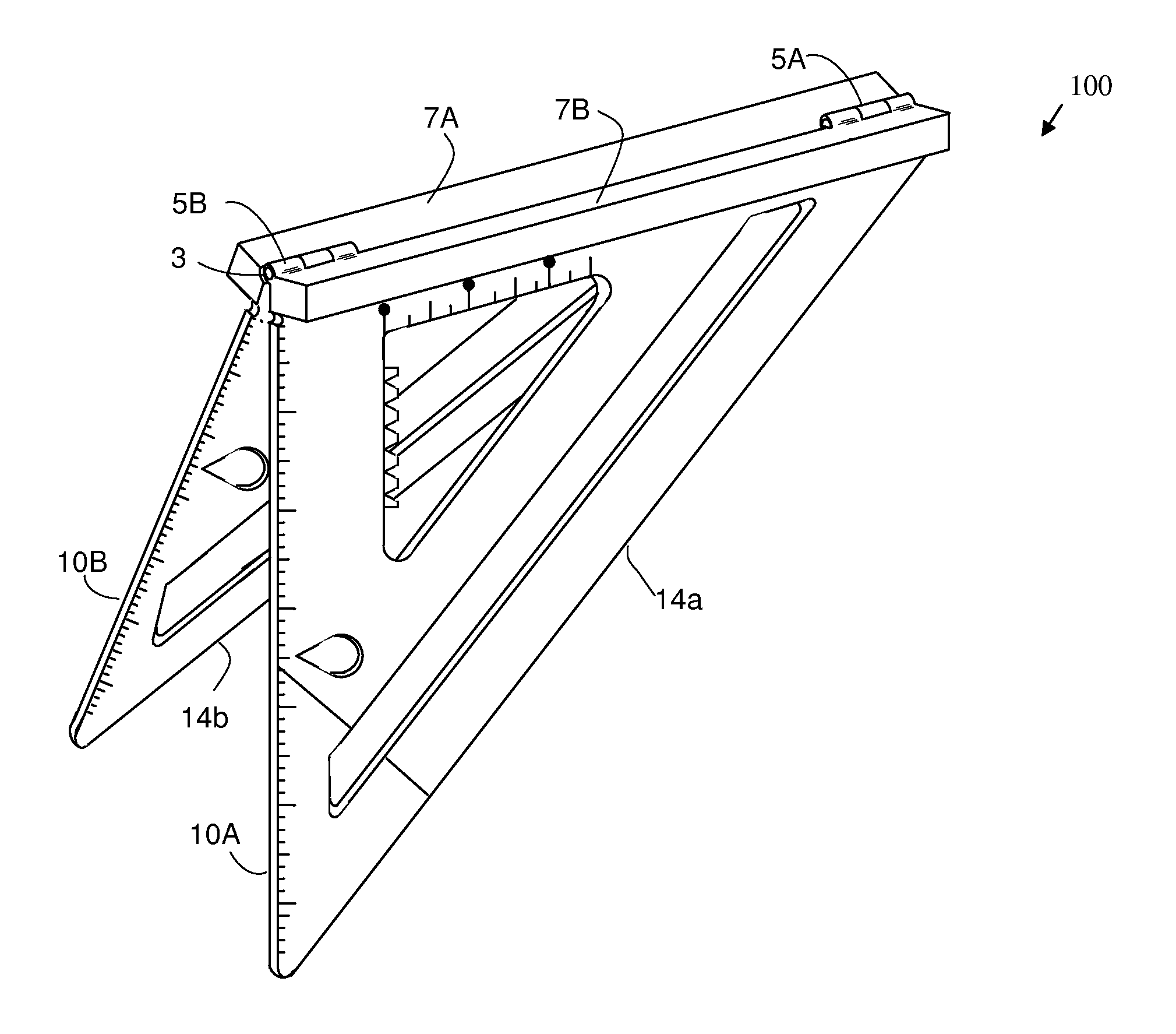
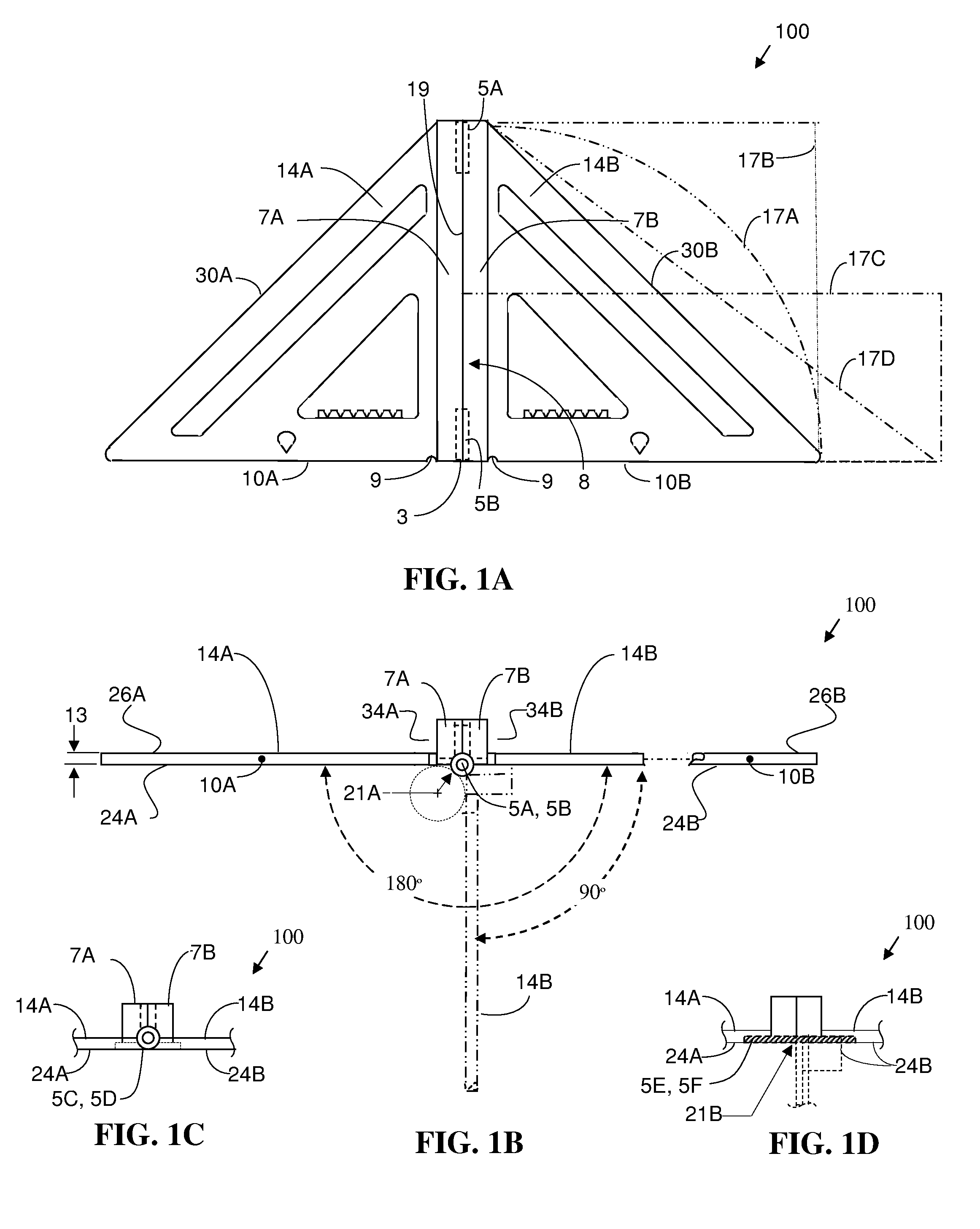
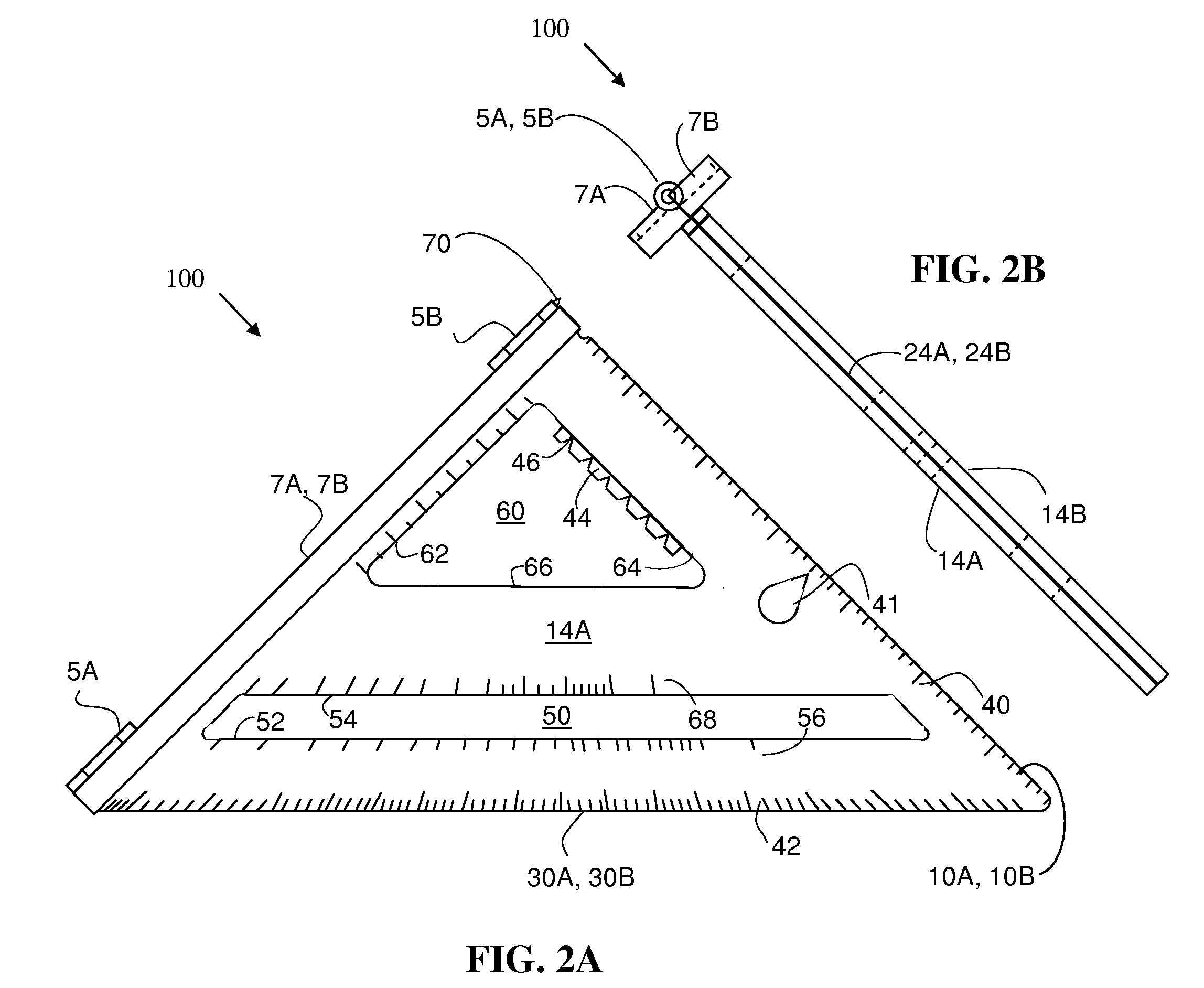
[0007]Beneficially, the present disclosure provides a multi-purpose tool that is geometrically and functionally configurable. In a closed position, the tool is compact for storage or for common functions such as a triangular measuring and marking tool saw guide. In a partially open position, the tool functions as a measuring and marking tool around edges of intersecting planes. And in its fully-open position of 180 degrees, the tool functions as a larger triangular measuring and marking device.
[0012]The tool is used by applying the tool to an object or work piece by initially placing the first member on a first plane and placing the second member on a second plane that intersects the first plane to form an edge and drawing a line along the straightedge of the first member on the first plane and along the straightedge of the second member on the second plane in a single step without having to reposition the measuring tool from the first plane to the second plane.

Problems solved by technology

However, trying to create a straight contiguous line that wraps around an edge can be a frustrating task because the lines are drawn on two different planes.
However, one-piece tools can be large, long, or bulky which only encourages handling damage and ultimately compromises the originally sought accuracy.

Method used


Image

  • Hinged measuring and marking device
  • Hinged measuring and marking device
  • Hinged measuring and marking device

Examples


Embodiment Construction

[0024]Reference will now be made in detail to the preferred embodiments of the invention. Examples of the preferred embodiment are illustrated in the accompanying drawings. While the invention will be described in conjunction with the preferred embodiments, it is understood that the invention is not limited to these embodiments. Rather, the invention is intended to cover alternatives, modifications and equivalents, which may be included within the spirit and scope of the invention, as defined by the appended claims. Additionally, in the following detailed description of the present disclosure, numerous specific details are set forth in order to provide a thorough understanding of embodiments of the present invention. However, it will be apparent to one of ordinary skill in the art that the present invention may be practiced without these specific details. In other instances, well-known methods, procedures, components, and operations have not been described in detail so as not to unn...


PUM


Abstract

An apparatus and method for a hinged measuring and marking device is disclosed herein. The device utilizes a first member, containing a flat surface with a straightedge for marking or measuring, coupled to a second member, also containing a flat surface with a straightedge for measuring or marking wherein the first member is coupled to the second member in a direction perpendicular to the straightedge of the first member. The straightedges of the first and second members are coplanar for marking an approximately contiguous line on a single plane or on two intersecting planes. The first member and the second member can be rotated between 0 and 180 degrees with respect to each other to accommodate marking a line on the two intersecting planes.

Description

REFERENCE TO RELATED APPLICATIONS[0001]This application claims priority to provisional application, Ser. No. 61 / 113,596, filed Nov. 11, 2008, which application is also incorporated herein by its reference, in its entirety.FIELD OF THE INVENTION[0002]The present disclosure relates generally to a measuring device and more particularly to a multi-purpose measuring and marking device.DESCRIPTION OF THE RELATED ART[0003]A desirable goal for constructing or rough framing a building or home project, for building a piece of furniture, for general carpentry, or other similar tasks is to create orthogonal, straight, and / or level lines. The lines can refer to marking lines, or the placement of a structure. The vast majority of buildings, rooms, furniture and other objects are built in an orthogonal manner, e.g., involving right (90 degree) angles with surfaces that are perpendicular to each other. An intersection of two planes, such as two walls in a room, creates an edge. While an intersectio...

Claims


Application Information

Patent Timeline
Patent Type & Authority Applications(United States)
IPC IPC(8): B43L7/12
CPCB25H7/00B43L7/005B43L7/0275B43L7/12G01B3/566B43L9/007B43L13/002G01B3/04B43L7/125
Inventor ATWOOD, RAYMOND E.
Owner ATWOOD RAYMOND E
Learn More