
Elastic curve ruler

An elastic curve and elastic technology, applied in the field of elastic curve ruler, can solve the problems of not easy to control, inconvenient to operate, inconvenient to carry, etc.

Inactive Publication Date: 2007-08-15
王佐良
View PDF0 Cites 8 Cited by
  • Summary
  • Abstract
  • Description
  • Claims
  • Application Information

AI Technical Summary

Problems solved by technology

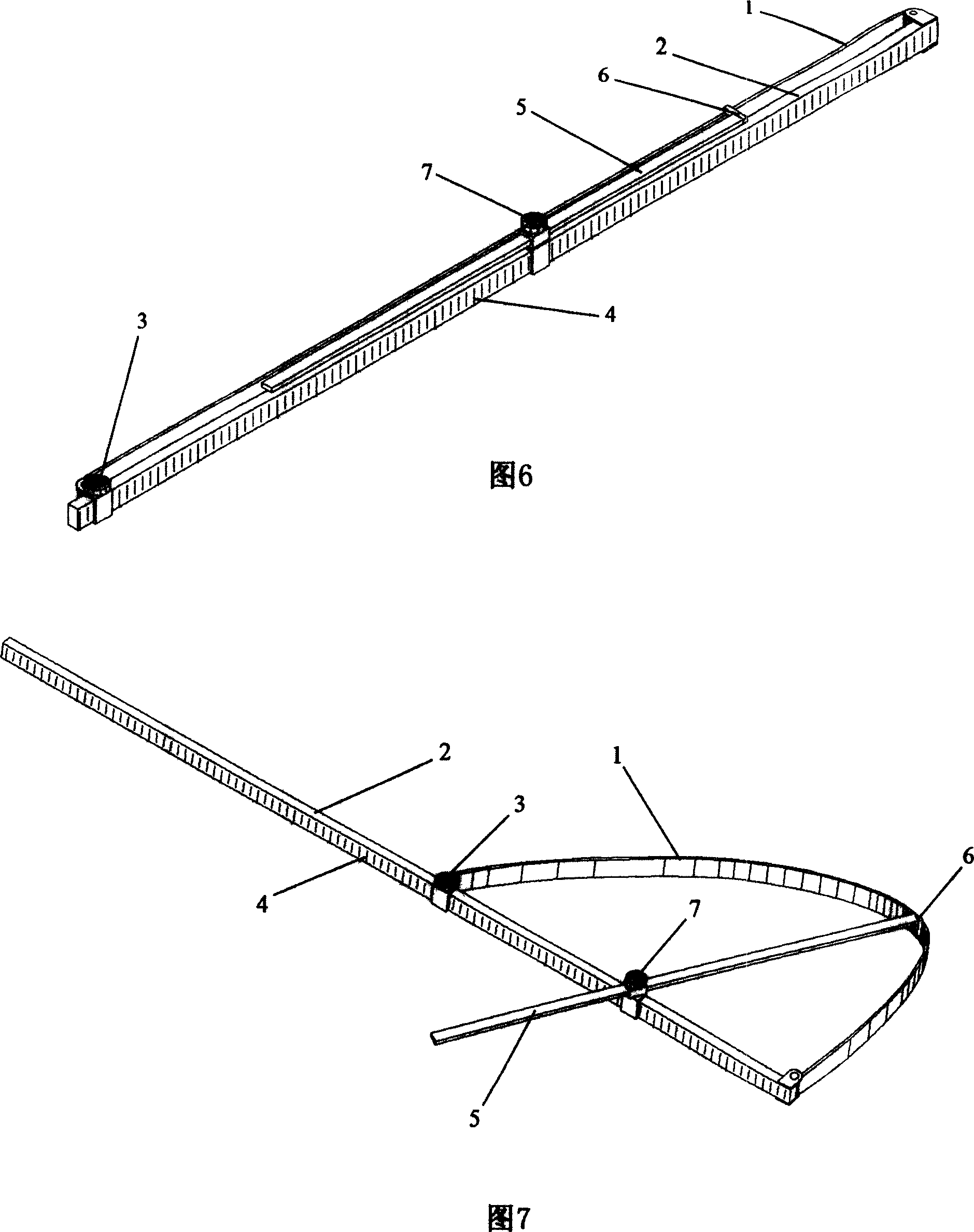
[0003] The purpose of the present invention is to overcome the shortcomings of the existing linear flexible curve ruler, which are inconvenient to operate, difficult to control during use, and the cloud-shaped curve ruler is large in size and inconvenient to carry, etc., to design a curved ruler that can freely change the curvature and fix the curve ruler body Shape, easy to operate, flexible, wide application range, and small size, easy to carry curve ruler, its technical solution: to rotate one end of the ruler body made of elastic and flexible material axially Connected to one end of the ruler beam, the other end is axially connected to the sliding bolt, the sliding bolt can slide on the ruler beam and lock its position on the ruler beam, so as to adjust the curvature of the ruler body; the other end of the ruler body It can also be connected to a ruler rod by axial rotation. The ruler rod is connected to the ruler beam through a sliding bolt. The sliding bolt can slide on the ruler beam and lock its position on the ruler beam. The ruler rod can slide on the sliding bolt and Rotate, and can be locked by the sliding bolt, so as to adjust the curvature of the ruler body; thus, two different simple curve rulers are obtained, and these two curve rulers can theoretically be adjusted from a straight line to a curvature equal to that of the ruler body The regular curve of the curvature of the circle whose length is the circumference; in order to further increase the control of the ruler body to adjust more complex curves, a sliding bolt can be added on the ruler beam, and a ruler arm is set on the sliding bolt , the sliding bolt can also slide on the ruler beam and lock its position on the ruler beam, the added ruler arm can slide and rotate on the slider bolt, and can be locked by the slider bolt, and the ruler body can be pushed by the ruler arm to To obtain more complicated curves, an arm claw can also be designed at one end of the ruler arm, which can grasp the ruler body and push or pull the ruler body by adjusting the length of the ruler arm, so as to obtain curves with different curvatures; in order to ensure the ruler rod, The ruler arms can be well locked by their own sliding bolts. The surfaces of the ruler beam, ruler rod and ruler arm can be frosted to increase friction. However, due to the elasticity of the ruler body, when the curve ruler uses the ruler rod, The requirements for the sliding bolt used to lock the ruler are very high. In order to prevent the situation that the sliding bolt cannot lock the ruler well due to repeated use, a pull rod can be installed on the curved ruler with the ruler. One end of the ruler is axially rotated at one end of the ruler body, and the other end is axially rotated at the other end of the ruler body through a fastening bolt, and the pull rod can slide on the fastening bolt and be locked by the fastening bolt, thereby eliminating the The elastic force of the ruler rod; in order to reduce the size of the curved ruler when it is not in use, the above-mentioned curved rulers are designed with reference to the design idea of ​​"Swiss Army Knife". The beams are overlapped together, and the body of the ruler can be parallel to the ruler beam and close to the ruler beam. In this way, when not in use, each of the above-mentioned curved rulers can shrink into a ruler-like size, which greatly enhances the convenience of carrying; in addition , both the ruler body and the ruler beam can be provided with scale lines, the scale lines on the ruler body can measure or grasp the length of the drawn curve segment, and the scale lines on the ruler beam can make the ruler beam have the function of a straightedge

Method used


Image

  • Elastic curve ruler
  • Elastic curve ruler
  • Elastic curve ruler

Examples


Embodiment Construction

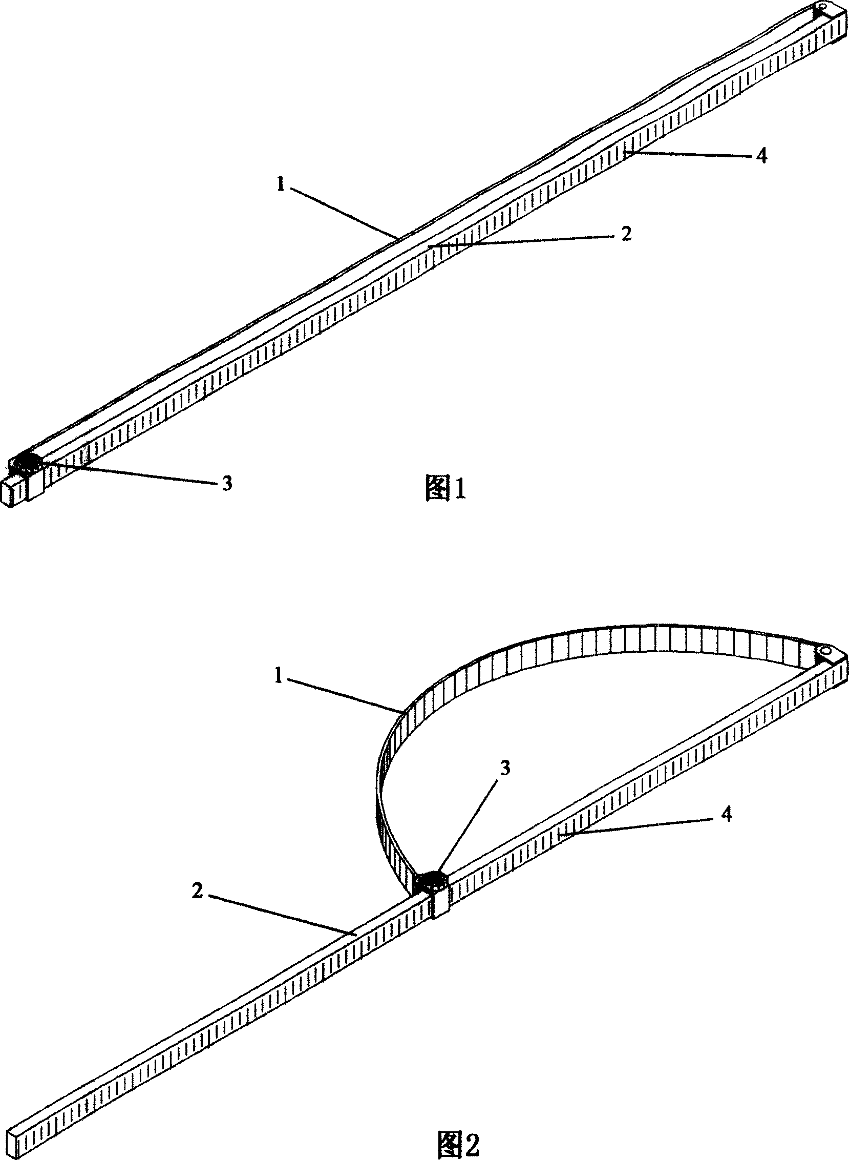
[0025] With reference to accompanying drawings 1 and 2, one end of the ruler body 1 is axially rotatably connected to one end of the ruler beam 2, and the other end is axially rotatably connected to the sliding bolt 3, and the sliding bolt 3 can slide on the ruler beam 2 and lock it on the ruler beam 2. The position on the beam 2 is used to adjust the curvature of the ruler body, thereby obtaining a simple curve ruler, which can theoretically adjust the curvature from a straight line to a circle whose circumference is equal to the length of the ruler body regular curve.

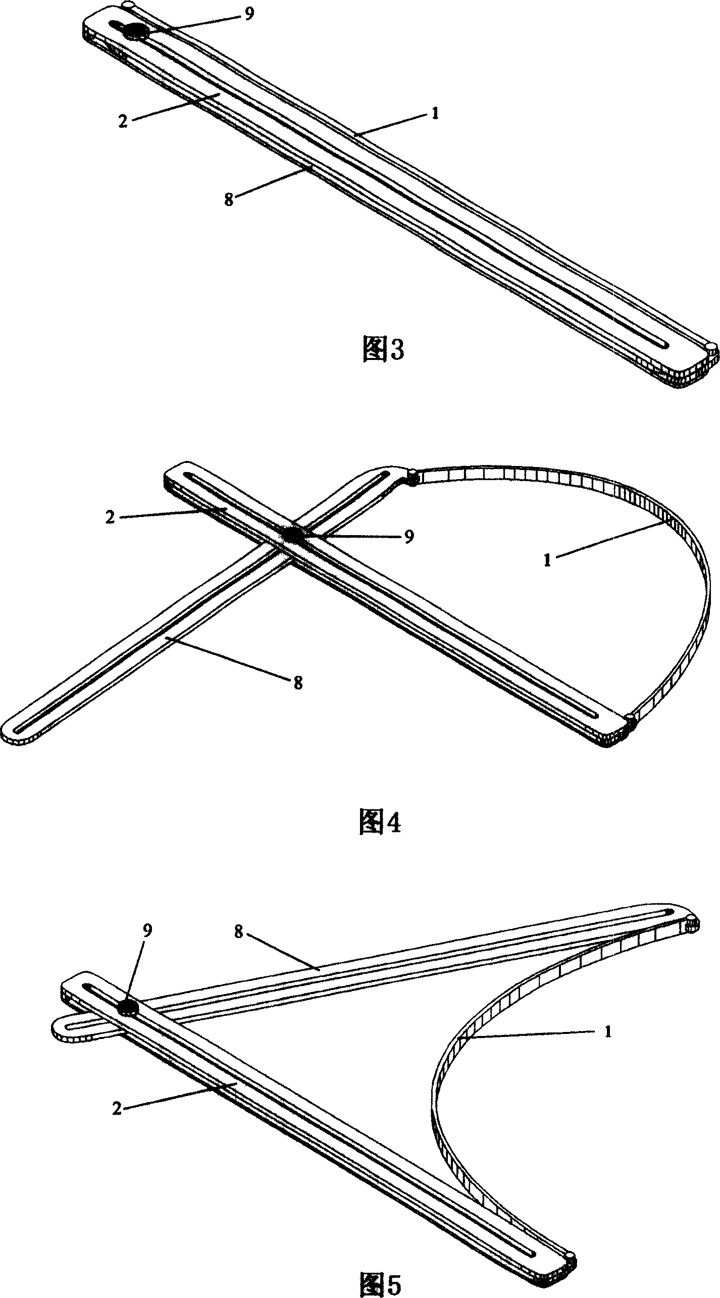
[0026] Referring to Figures 3, 4, and 5, the other end of the ruler body 1 can also be connected to the ruler rod 8 by axial rotation, and the ruler rod 8 is connected to the ruler beam 2 through the sliding bolt 9, and the sliding bolt 9 can slide on the ruler beam 2 And lock its position on the ruler beam 2, the ruler rod 8 can slide and rotate on the slide bolt 9, and can be locked by the slide bolt 9, thu...


PUM


Abstract

The invention relates to a flexible curvature scale, which axially rotationally connects one end of flexible ruler on one end of the ruler beam while another end is axially rotationally connected with a sliding bolt. The sliding bolt can slide and be locked on the ruler beam which is disposed with another sliding bolt and ruler arm, while the sliding bolt can slide and be locked on the ruler beam. The ruler beam can slide, rotate and lock on the sliding bolt. The invention also comprises a ruler rod and a drawing rod, to adjust different complex curvatures via the match between the ruler rod, the drawing rod, the ruler arm and the bolt. The inventive ruler rod, ruler arm and drawing rod can be folded into ruler beam or layered with the ruler beam, while the ruler body can be parallel with the ruler beam and contacted with the ruler beam. And when in free-state, the curvature ruler can be reduced into straight rule.

Description

technical field [0001] The present invention relates to an elastic curved ruler, which is a group of curved rulers whose curvature can be freely changed by utilizing the characteristics of elasticity and flexibility of the curved ruler body, and is used to solve the problem that the curvature of the cloud-shaped curved ruler cannot be solved. Change, linear flexible curve ruler is not convenient to use, and the flexibility is poor. Background technique [0002] The existing cloud-shaped curve ruler (also called cloud-shaped gauge) is made of hard plastic, and there are some common fixed curves with different curvatures on it. Users can form curves of different shapes by finding curve segments that meet their needs on the fixed curves. Or circular line, because the curvature cannot be changed freely, so it has great limitations in use, the curve drawn is prone to not smooth phenomenon, and the volume is large, which is not convenient to carry; other linear flexible curve rule...

Claims


Application Information

Patent Timeline
Patent Type & Authority Applications(China)
IPC IPC(8): B43L11/00G01B3/10
Inventor 王佐良
Owner 王佐良
Learn More