

Purge gas assembly
Active Publication Date: 2010-06-10
ULVAC INC
View PDF39 Cites 7 Cited by
- Summary
- Abstract
- Description
- Claims
- Application Information
AI Technical Summary
Benefits of technology
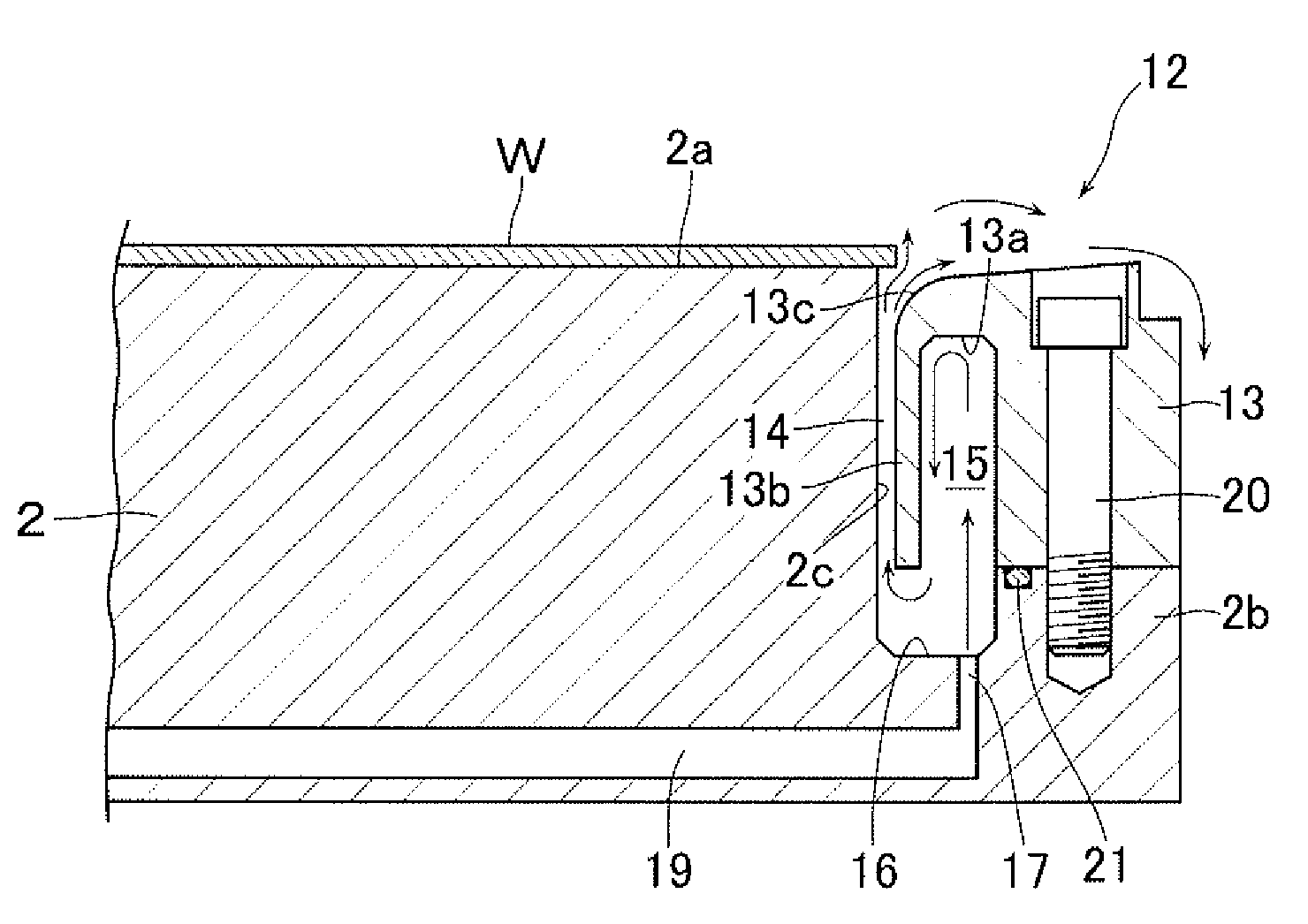
[0010]According to this invention, the purge gas is distributed in the circumferential direction inside the distribution chamber before being supplied to the gas ejection passage. Here, since the distribution chamber is constituted by the annular groove that is formed in the purge ring, that inside portion of the purge ring which lies on the outside of the gas ejection passage and which ordinarily becomes a dead space can be effectively utilized as a space for disposing therein the distribution chamber, and the distribution chamber can be secured large enough in cross-sectional area. As a consequence, without using a separate member to accelerate the distribution in the circumferential direction such as the coiled member in the above conventional example, the distribution of the purge gas in the circumferential direction inside the distribution chamber can be made uniform and the purge gas can therefore be ejected uniformly from the gas ejection passage over the entire circumference thereof.
[0011]Even if the heat of the substrate stage is transmitted to the purge ring, the purge ring can be efficiently cooled by the purge gas that flows through the distribution chamber within the purge ring. Therefore, without constituting the purge ring by a plurality of upper and lower members as in the above conventional example, the upper surface temperatu
Problems solved by technology
As a result, the processing by the processing gas will not reach the outer edge of the substrate.
Unless the purge gas is ejected uniformly out of the gas ejection passage over the entire circumference thereof, there is a possibility that the film distribution on the surface of the substra
Method used
View moreImage
Smart ImageViewing Examples

Examples
Example
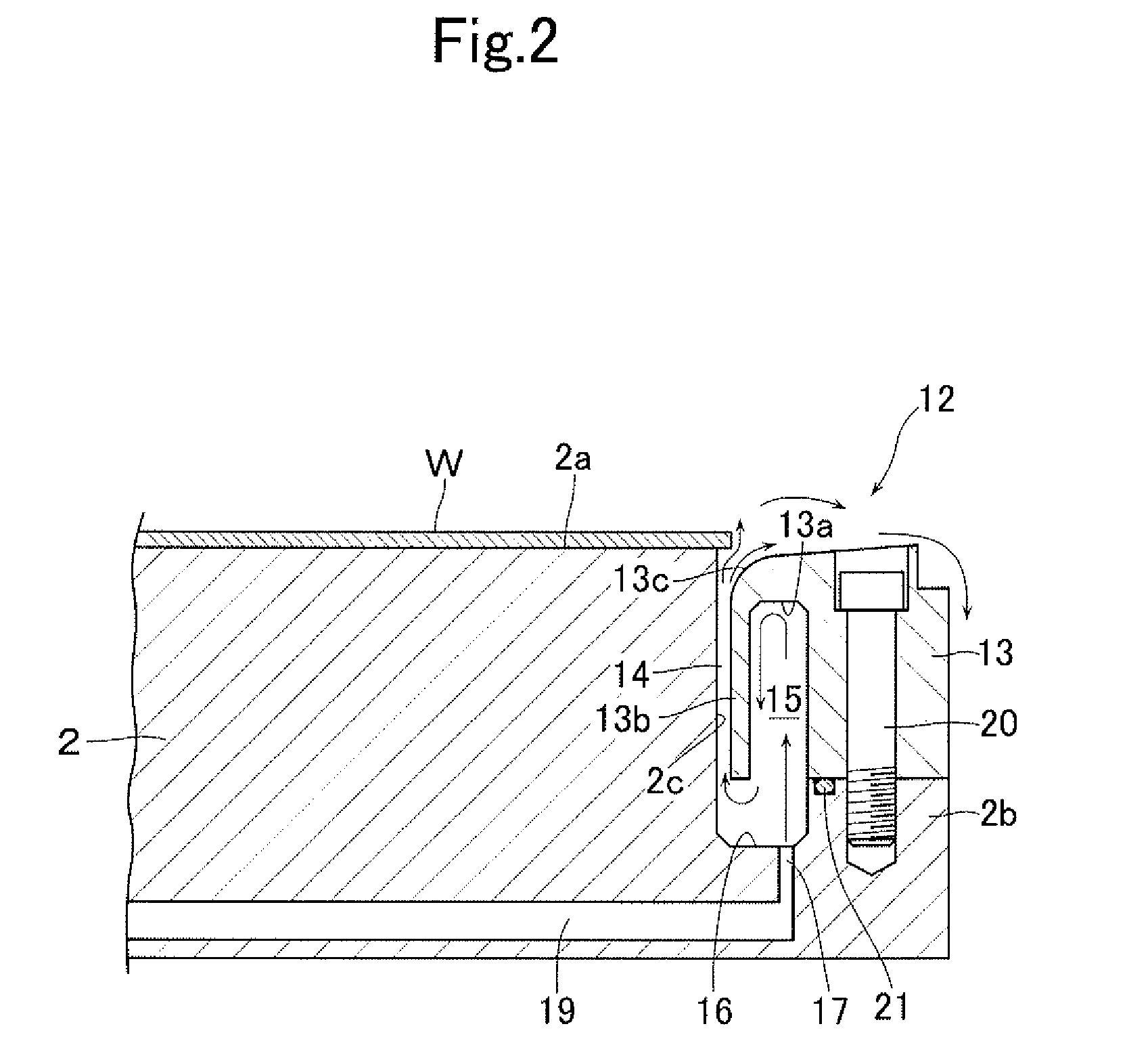
[0033]1 processing chamber[0034]2 substrate stage[0035]2a substrate mounting surface[0036]2b shoulder portion[0037]2c stepped circumferential surface[0038]12 purge gas assembly[0039]13 purge ring[0040]13a annular groove[0041]13b inner circumferential wall[0042]13c enlarged diameter portion[0043]14 gas ejection passage[0044]15 distribution chamber[0045]W substrate
Login to View More PUM
| Property | Measurement | Unit |
|---|---|---|
| Diameter | aaaaa | aaaaa |
Abstract
In a purge gas assembly provided: in an outer circumference portion of a substrate stage, with a shoulder portion offset downward below a substrate mounting surface on an upper end of the substrate stage; a purge ring enclosing a stepped circumferential surface between the substrate mounting surface and the shoulder portion; and an annular gas ejection passage for ejecting the purge gas, the gas ejecting passage being defined between the stepped circumferential surface and an inner circumferential surface of the purge ring, an arrangement is made such that the purge gas can be ejected uniformly from the gas ejection passage over the entire circumference thereof and that the deposition of a film on an upper surface of the purge ring can also be restricted, and further that the construction is simplified. The purge ring has formed therein an annular groove which recesses from a lower surface thereof upward.
Description
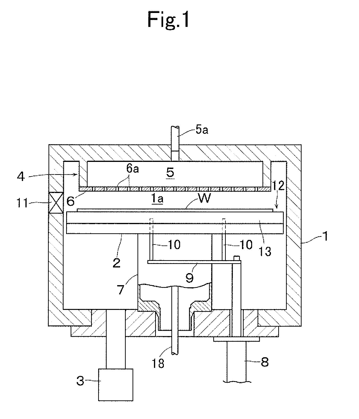
TECHNICAL FIELD[0001]The present invention relates to a purge gas assembly used in a processing apparatus which performs processing of film forming and the like on a surface mainly of a semiconductor substrate.BACKGROUND ART[0002]Conventionally, there is known a processing apparatus in which a substrate to be processed is placed on a substrate stage disposed inside an evacuated processing chamber and in which film-forming processing is performed by CVD method to form a thin film on a surface of the substrate. In this kind of processing apparatus, in case the processing to be performed on the surface of the substrate extends to the outer edge of the substrate so that a film is consequently deposited there, there is the following possibility, i.e., due to the possible peeling off of the film deposited on the outer edge, a bad effect such as particles, contamination and the like will be given to the subsequent processes such as chemical mechanical polishing (CMP) and the like.[0003]As ...
Claims
Login to View More Application Information
Patent Timeline
 IPC IPC(8): B05C11/00
CPCC23C16/45519H01L21/68735C23C16/4585C23C16/455H01L21/205
InventorKAGAMI, TSUYOSHIIRINO, OSAMUKATO, NOBUYUKIUSHIKAWA, HARUNORI
OwnerULVAC INC