Purge gas assembly

a technology of purge gas and assembly, which is applied in the direction of liquid surface applicators, chemical vapor deposition coatings, coatings, etc., can solve the problems of abnormal film distribution on the surface of the substrate, the inability to make so large sectional area of the recessed groove, and the processing gas cannot reach the outer edge of the substrate, etc., to achieve convenient maintenance, secure large cross-sectional area, and efficient cooling

Active Publication Date: 2013-02-19
ULVAC INC
View PDF45 Cites 3 Cited by
  • Summary
  • Abstract
  • Description
  • Claims
  • Application Information

AI Technical Summary

Benefits of technology

[0011]According to this invention, the purge gas is distributed in the circumferential direction inside the distribution chamber before being supplied to the gas ejection passage. Here, since the distribution chamber is constituted by the annular groove that is formed in the purge ring, that inside portion of the purge ring which lies on the outside of the gas ejection passage and which ordinarily becomes a dead space can be effectively utilized as a space for disposing therein the distribution chamber, and the distribution chamber can be secured large enough in cross-sectional area. As a consequence, without using a separate member to accelerate the distribution in the circumferential direction such as the coiled member in the above conventional example, the distribution of the purge gas in the circumferential direction inside the distribution chamber can be made uniform and the purge gas can therefore be ejected uniformly from the gas ejection passage over the entire circumference thereof.
[0030]Further, in the above embodiment, the purge ring 13 is so arranged that the lower surface portion outside the seal ring 21 is in intimate contact with the upper surface of the shoulder portion 2b. It is, however, possible to arrange that the area of contact between the purge ring 13 and the shoulder portion 2b is minimized to thereby restrict the heat transmission from the substrate stage 2 to the purge ring 13.

Problems solved by technology

As a result, the processing by the processing gas will not reach the outer edge of the substrate.
Unless the purge gas is ejected uniformly out of the gas ejection passage over the entire circumference thereof, there is a possibility that the film distribution on the surface of the substrate becomes abnormal.
However, due to the dimensional restriction in the shoulder portion, the cross sectional area of the recessed groove cannot be made so large, so that the distribution of the purge gas in the circumferential direction cannot be made uniform by the recessed groove alone.

Method used


Image

  • Purge gas assembly
  • Purge gas assembly
  • Purge gas assembly

Examples


Embodiment Construction

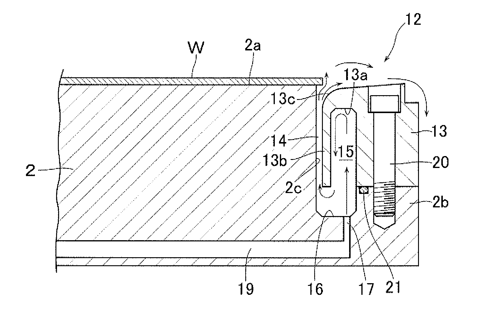
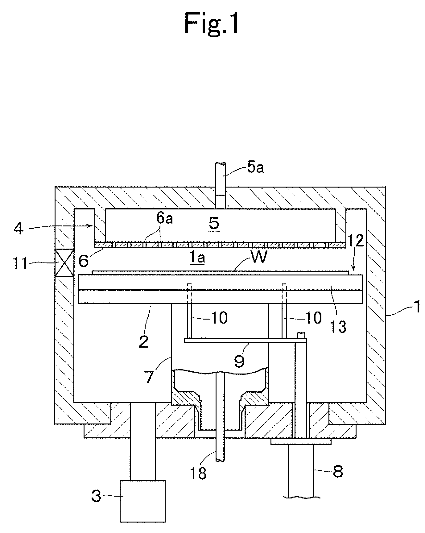
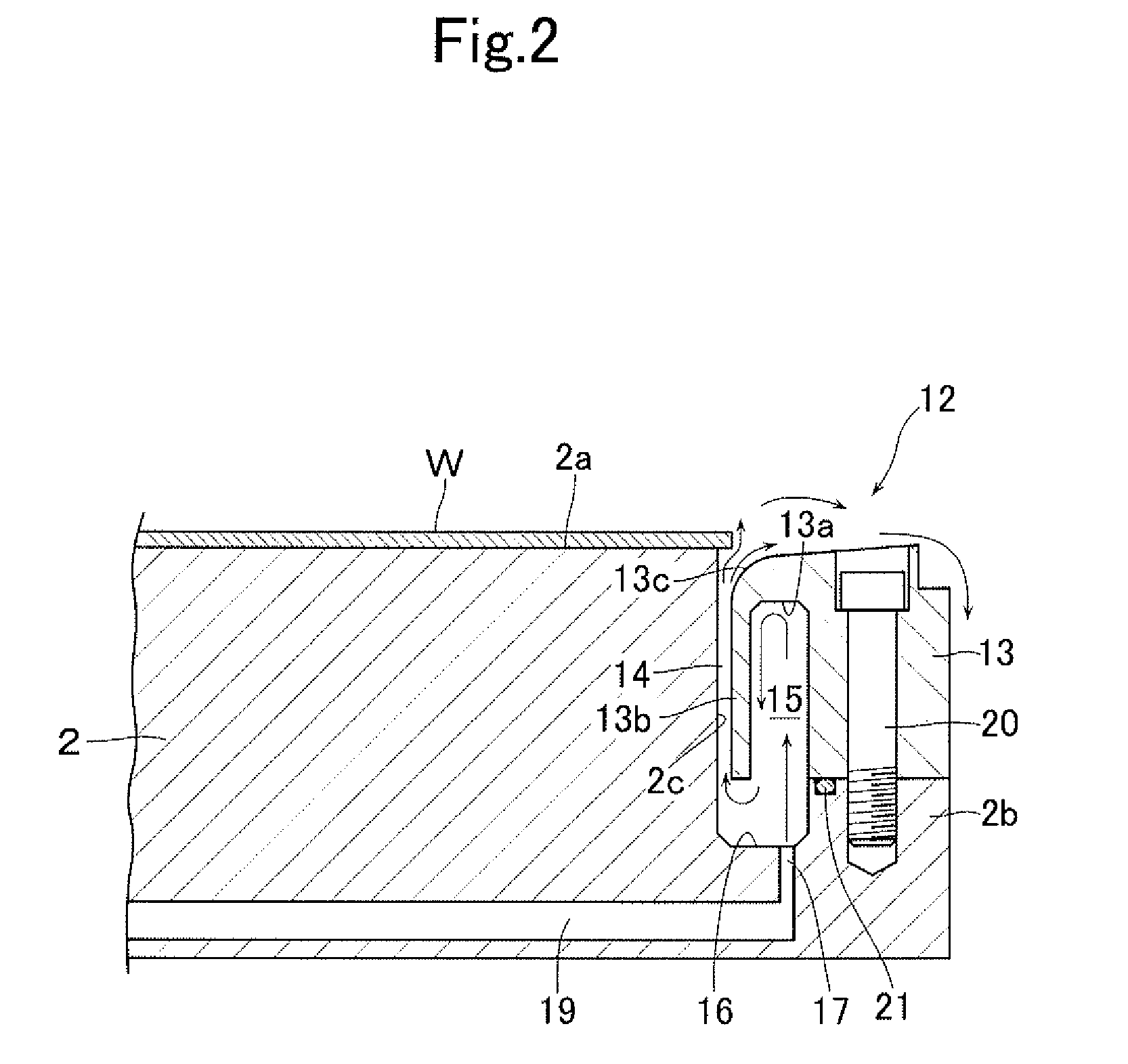
[0016]FIG. 1 shows a processing apparatus which is provided with a purge gas assembly according to an embodiment of this invention. This processing apparatus is provided with a vacuum chamber 1 defining a processing chamber a, and a substrate stage 2 which is disposed in the processing chamber 1a. A film-forming processing is thus performed to form a thin film by CVD method on a surface of a substrate W of silicon wafer, glass and the like which is placed on the substrate stage 2.

[0017]The vacuum chamber 1 is evacuated by an evacuating means 3 which is connected to a bottom portion of the vacuum chamber 1. The processing chamber 1a is provided at its ceiling portion with a gas supply means 4 which supplies the processing chamber 1a with a process gas made up of a raw gas and a reactant gas. The gas supply means 4 is made up of a gas diffusion chamber 5 into which the process gas is supplied through a supply pipe 5a, and a shower plate 6 on a lower surface of the gas diffusion chambe...


PUM

PropertyMeasurementUnit
widthaaaaaaaaaa
diameteraaaaaaaaaa
diameteraaaaaaaaaa

Abstract

In a purge gas assembly provided: in an outer circumference portion of a substrate stage, with a shoulder portion offset downward below a substrate mounting surface on an upper end of the substrate stage; a purge ring enclosing a stepped circumferential surface between the substrate mounting surface and the shoulder portion; and an annular gas ejection passage for ejecting the purge gas, the gas ejecting passage being defined between the stepped circumferential surface and an inner circumferential surface of the purge ring, an arrangement is made such that the purge gas can be ejected uniformly from the gas ejection passage over the entire circumference thereof and that the deposition of a film on an upper surface of the purge ring can also be restricted, and further that the construction is simplified. The purge ring has formed therein an annular groove which recesses from a lower surface thereof upward.

Description

[0001]This application is a national phase entry under 35 U.S.C. §371 of PCT Patent Application No. PCT / JP2008 / 057846, filed on Apr. 23, 2008, which claims priority under 35 U.S.C. §119 to Japanese Patent Application No. 2007-124860, filed May 9, 2007, both of which are incorporated by reference.TECHNICAL FIELD[0002]The present invention relates to a purge gas assembly used in a processing apparatus which performs processing of film forming and the like on a surface mainly of a semiconductor substrate.BACKGROUND ART[0003]Conventionally, there is known a processing apparatus in which a substrate to be processed is placed on a substrate stage disposed inside an evacuated processing chamber and in which film-forming processing is performed by CVD method to form a thin film on a surface of the substrate. In this kind of processing apparatus, in case the processing to be performed on the surface of the substrate extends to the outer edge of the substrate so that a film is consequently de...

Claims


Application Information

Patent Timeline
Patent Type & Authority Patents(United States)
IPC IPC(8): C23C16/455C23F1/00C23C16/458H01L21/306C23C16/22C23C16/06
CPCC23C16/45519C23C16/4585H01L21/68735C23C16/455H01L21/205
Inventor KAGAMI, TSUYOSHIIRINO, OSAMUKATO, NOBUYUKIUSHIKAWA, HARUNORI
Owner ULVAC INC
Why Eureka
Try Eureka