
Flying object having one body wings

a flying object and one body technology, applied in the field of flying objects, can solve the problems of aerodynamic requirements, increased weight of the nozzle assembly, increased drag generation, etc., and achieve the effect of reducing the drag of the flying object and the weight of the flying obj

Active Publication Date: 2014-05-01
AGENCY FOR DEFENSE DEV
View PDF5 Cites 1 Cited by
  • Summary
  • Abstract
  • Description
  • Claims
  • Application Information

AI Technical Summary

Benefits of technology

The patent describes a way to make flying objects have less drag and be lighter by using a special covering with a space between it and the engine nozzle. This reduces heat transfer and can help the object fly more effectively.

Problems solved by technology

Thus, a free surface of the nozzle structure has no choice but to be bent, and thus, additional drag may be generated.
In case of fabricating the nozzle assembly to have improved heat resistance characteristics, the nozzle assembly is inevitably increased in weight.
Meanwhile, the fixed tail wing may be applied when aerodynamics requirements are limited relative to the foldable tail wing.
When a cant angle and straightness of the wing should be strictly limited, it is difficult to precisely form tolerance of a structure in which the fixed wing is bolt-fastened with the covering.
Thus, it is difficult to reduce weight of the covering.
Thus, in case of a missile having a high slenderness ratio, the center of gravity is positioned in a rear side of the flying object after the propulsion engine is burned, reducing stability of the flying object.
Also, the structure in which the wing is fastened or assembled to the covering has a problem in that components required for fastening or assembling are increased, fabrication costs are high, and a number of assembly processes is increased.

Method used


Image

  • Flying object having one body wings
  • Flying object having one body wings
  • Flying object having one body wings

Examples


Embodiment Construction

[0052]Description will now be given in detail of the exemplary embodiments, with reference to the accompanying drawings. For the sake of brief description with reference to the drawings, the same or equivalent components will be provided with the same reference numbers, and description thereof will not be repeated.

[0053]Hereinafter, a flying object including a covering-integrated wing in relation to the present embodiment will be described in detail with reference to the accompanying drawings. In the present disclosure, the same or similar elements although they are in different embodiments are given the like or similar reference numerals and a description thereof will be replaced by a first description. Singular forms “a”, “an” and “the” in the present disclosure are intended to include the plural forms as well, unless the context clearly indicates otherwise.

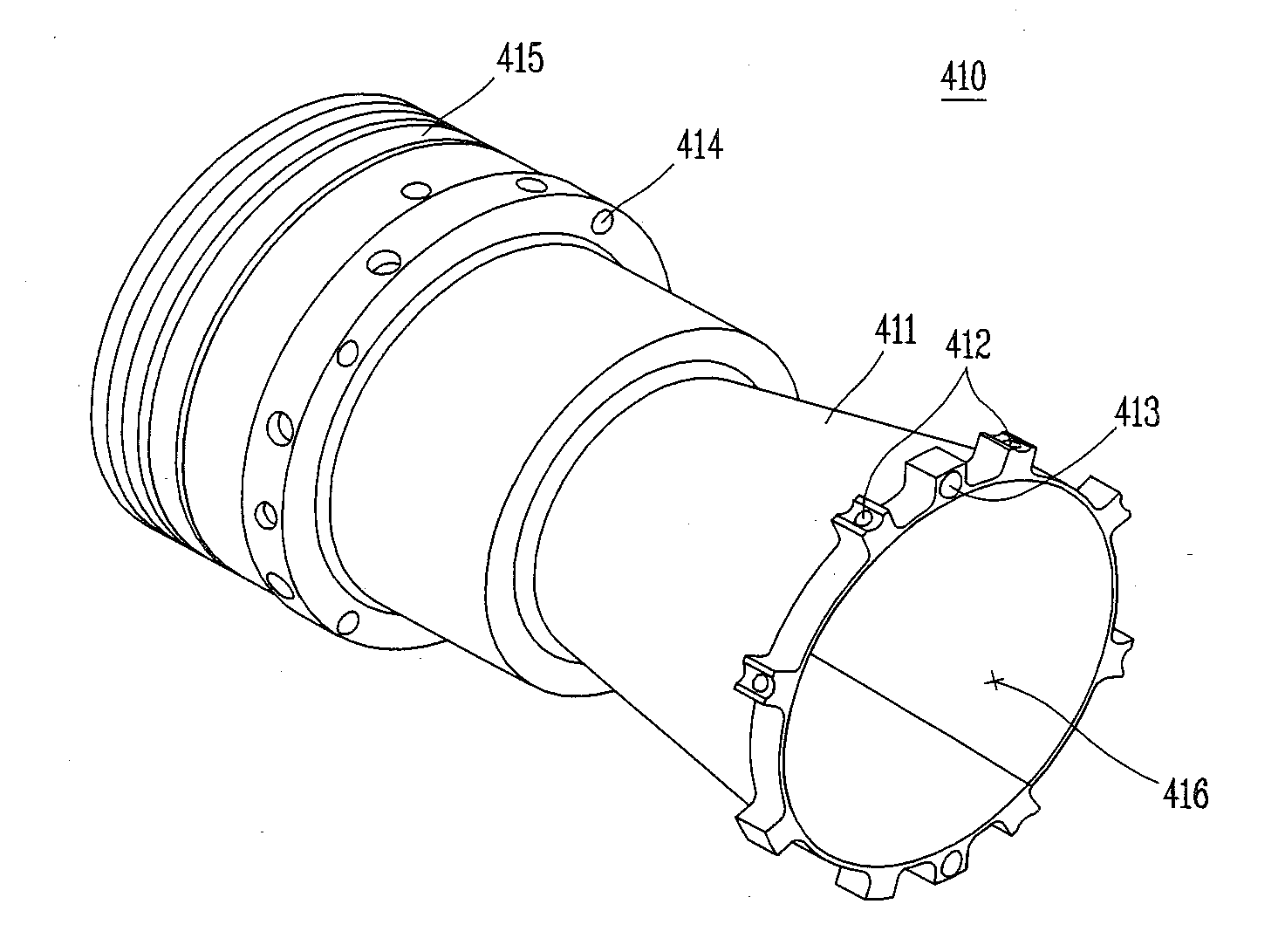
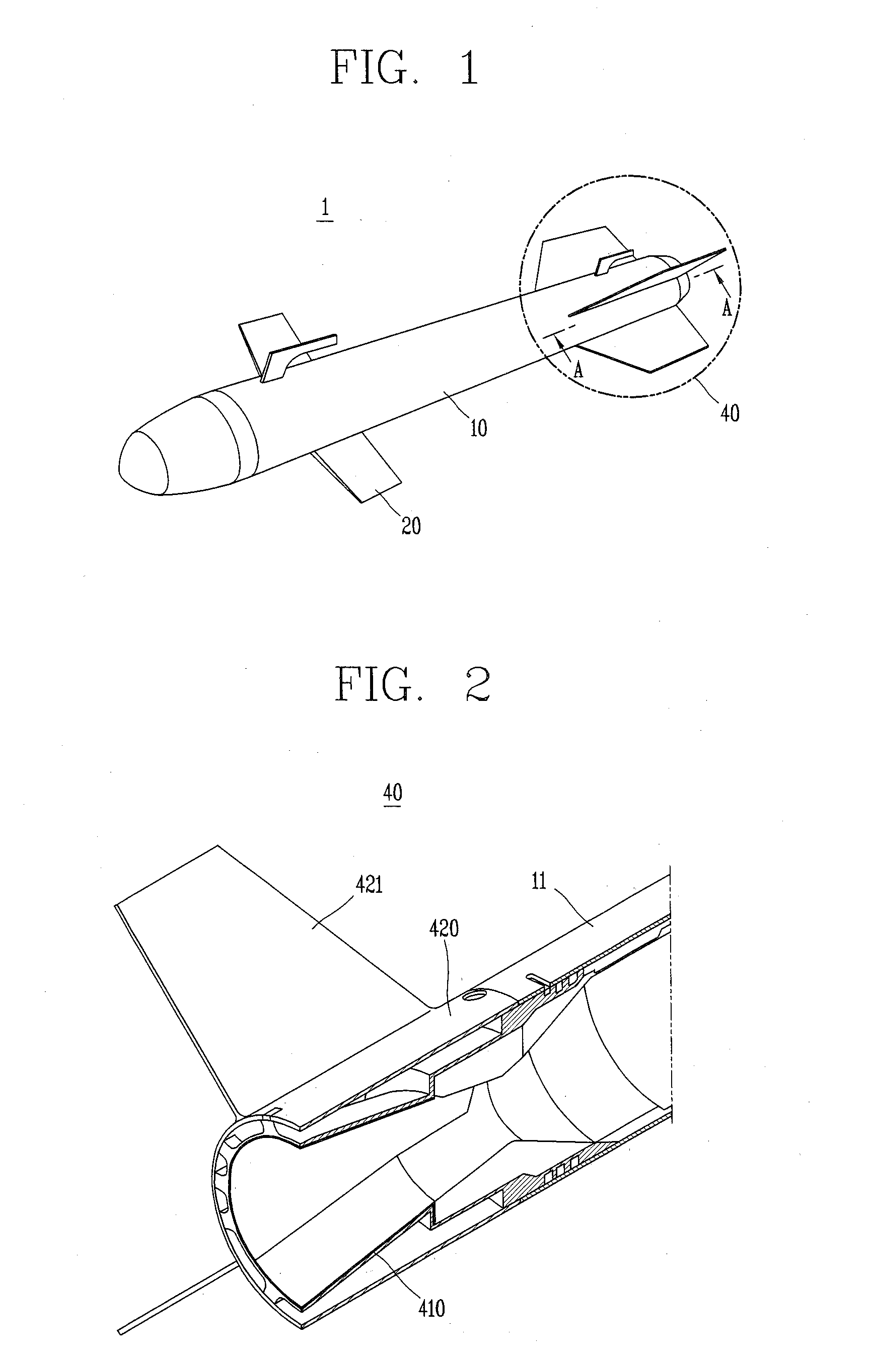
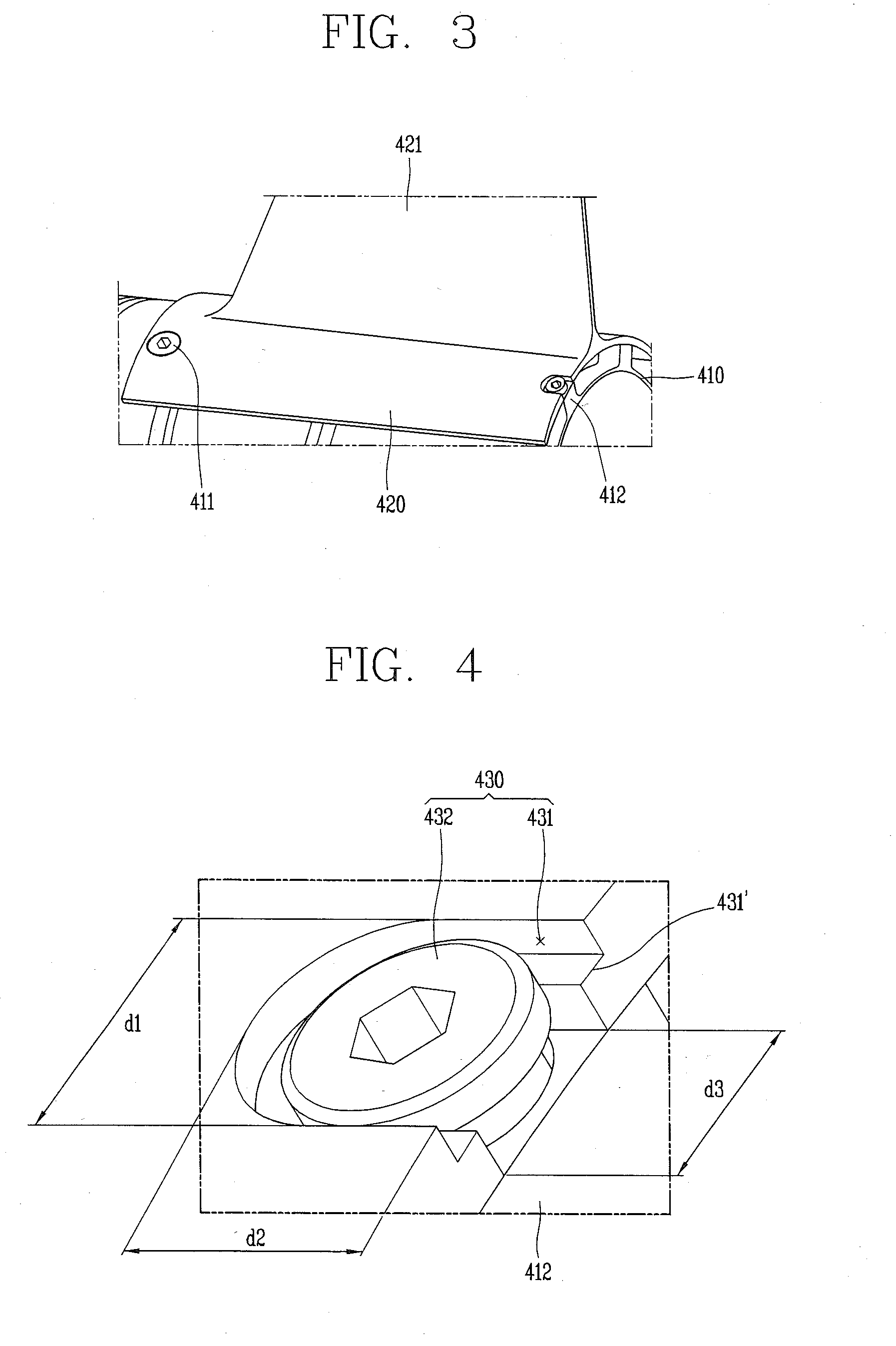
[0054]FIG. 1 illustrates a conceptual view of a flying object according to an embodiment of the present invention.

[0055]Refer...


PUM


Abstract

Disclosed is a flying object in which a covering unit and a wing unit installed in a nozzle assembly are integrally formed to form a smooth outer surface of the flying object, thus minimizing drag, and the covering unit and the nozzle assembly are fastened by using a fastening member having one end fastened to a slit, thereby preventing the flying object from being damaged by thermal deformation.

Description

CROSS-REFERENCE TO RELATED APPLICATION[0001]Pursuant to 35 U.S.C. §119(a), this application claims the benefit of earlier filing date and right of priority to Korean Application No. 10-2012-0119221, filed on Oct. 25, 2012, the contents of which is incorporated by reference herein in its entirety.BACKGROUND OF THE INVENTION[0002]1. Field of the Invention[0003]The present disclosure relates to a flying object having wings formed in one end of a body.[0004]2. Background of the Invention[0005]In order to maintain flying stability of a flying object such as a guide missile, a rocket, or the like, a control fin and a tail wing are installed in a main body of the flying object. In general, the tail wing is disposed to be adjacent to a nozzle assembly providing propulsive force of the flying object, and a plurality of tail wings are formed to maintain balance of the flying object.[0006]The tail wing installed in the flying object may be classified into a foldable tail wing and a fixed tail ...

Claims


Application Information

Patent Timeline
Patent Type & Authority Applications(United States)
IPC IPC(8): F42B15/00
CPCF42B15/00F42B10/06F42B15/10B64C1/26F42B10/04F42B10/08
Inventor PARK, SUNG HANLEE, KYUNG YONGKIM, YEUNG CHEOLKANG, KYOUNG TAI
Owner AGENCY FOR DEFENSE DEV
Learn More