Vulcanizing press for tire blanks provided with inductors

Active Publication Date: 2015-03-26
MICHELIN & CO CIE GEN DES ESTAB MICHELIN
View PDF3 Cites 1 Cited by
  • Summary
  • Abstract
  • Description
  • Claims
  • Application Information

AI Technical Summary

Benefits of technology

The invention aims to reduce the temperature and noise of an inductor. The design includes a connecting element with a smaller surface area than the component, which slows the transfer of heat. The space between the component and the connecting element reduces the area of contact, making it less likely for the inductor to strike the component. The positioning also reduces deformation and wear on the component. The armature is designed with elongated legs, which increases the time needed for the heat to reach the coil, reducing the maximum temperature attained. The invention allows for easy replacement of the wearing component separately from the armature and the component that is to be heated. The use of aramids absorbs vibrations and slows heat transfer, further reducing noise and wear.

Problems solved by technology

First of all, the component, which may reach a temperature of between 100 and 400° C., transmits a significant amount of heat to the armature which means that the coil, its insulators and its coatings have to be made from materials able to withstand high temperatures. The alternative is for the inductor to be fitted with cooling means. All of these solutions are very expensive.
This phenomenon may generate movements and impacts of the inductor against the component liable to generate noise in excess of 80 decibels.
It also generates wear on those surfaces of the armature that strike the component.
Now, the noise constitutes a nuisance to persons in the vicinity and the wear ultimately leads to replacement of the inductors, representing a significant cost and causing production down-time.
However, these solutions are expensive without always being effective.
It is therefore liable to move even more by rolling and rocking along its length against the curved part, thereby aggravating the phenomena of noise and of wear.
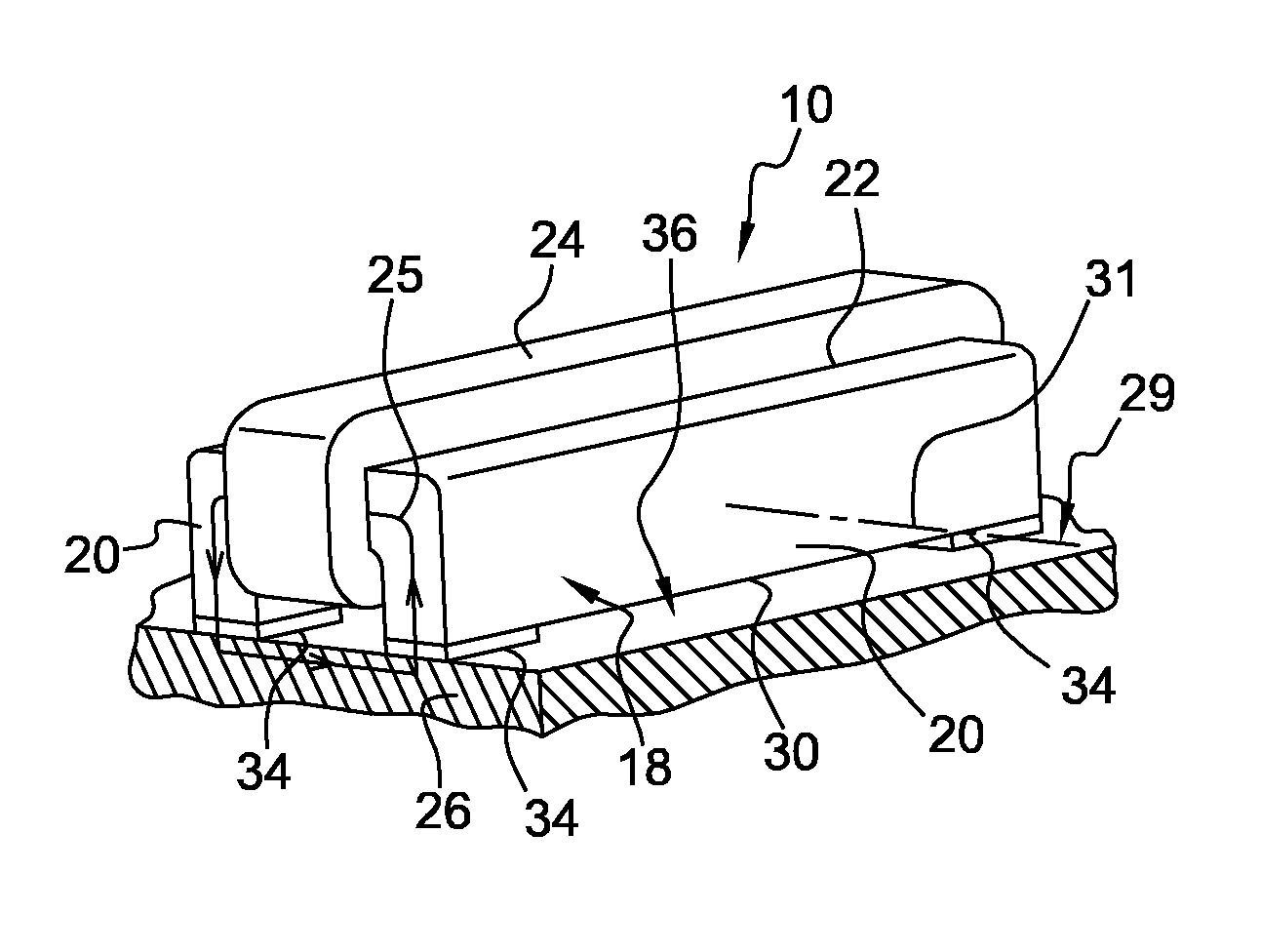
Thus, the reduced surface area of the connecting element or elements compared with that of the sole slows and limits the transmission of heat from the component to the armature.
In addition, the space between the sole and the component limits the area of contact between the two.
The noise and wearing of the surfaces of the armature that are in contact with the component are thus limited.
The possibilities of vibrating are also considerably limited.
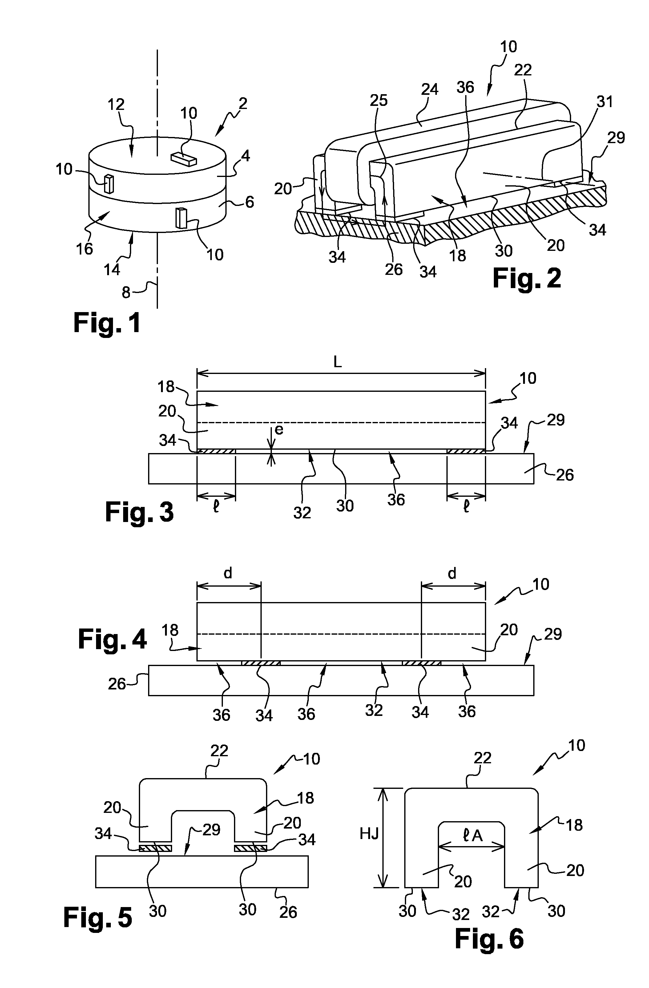
Nevertheless, when the inductor and the component to be heated have a significant length, for example in excess of 300 mm, and the connecting elements are contiguous with the ends of the sole, two additional unfavourable phenomena may arise.
The first is that the deflection adopted by the component under the effect of the asymmetric thermal expansion may exceed the height of the connecting elements, i.e. the thickness of the space, and thus recreate noise and wear.
The second is that the alternating electromagnetic forces may lead to alternating deformations of the armature with a significant amplitude, for example in excess of 0.1 mm, and cause it to collide with the curved part of the component which, once again, recreates the noise and the wear.
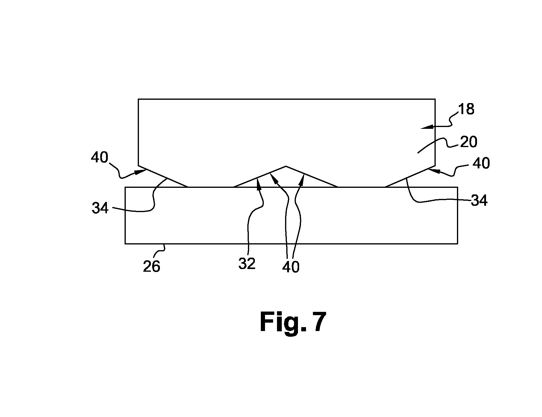
However, it is often the case that these connecting elements end up wearing out, which then means that the entire armature or the entire component that is to be heated has to be replaced or remachined.
Thus, the armature is given particularly long legs, as this keeps a large part of the inductor away from the component that is to be heated and therefore slows the transfer of heat from the one to the other.
In addition, if the armature does not need to be in permanent contact with the component, this arrangement means that the armature is subjected to particularly pronounced transient thermal conditions.

Method used


Image

  • Vulcanizing press for tire blanks provided with inductors
  • Vulcanizing press for tire blanks provided with inductors
  • Vulcanizing press for tire blanks provided with inductors

Examples


Embodiment Construction

[0042]FIGS. 1 to 3 illustrate a press 2 used for curing green tire blanks for wheels. These tires are intended for example for vehicles of the light vehicle type, passenger cars, utility vehicles, heavy vehicles or even construction plant machinery.

[0043]The press 2 comprises two parts, an upper part 4 and a lower part 6, which are able to move in sliding relative to one another in the vertical direction which is that of a main axis of symmetry 8 of the press, in order to open and close the press. These parts contain mold portions that are used to give the tire its definitive shape when the green tire blank is being vulcanized.

[0044]To this end, the press is equipped with inductors 10 arranged against various parts of the press, on the external faces thereof, in order to afford the heat necessary to vulcanize the rubber which forms most of the green tire blank held in the press. Provision may thus be made for one or more inductors to be positioned against an upper 12 or lower 14 hor...


PUM

PropertyMeasurementUnit
Lengthaaaaaaaaaa
Widthaaaaaaaaaa
Heightaaaaaaaaaa

Abstract

The vulcanizing press for curing green tire blanks having:a component,at least one inductor comprising an armature having two free ends exhibiting soles which are able to close an electromagnetic loop through the component, andfor each sole, at least one connecting element connecting the sole to the component and forming between the two of them at least one space, the connecting element or elements associated with the sole occupying in total less than half of a length of the sole.

Description

[0001]This application is a 371 national phase entry of PCT / FR2012 / 052888, filed 12 Dec. 2012, which claims benefit of FR 1161925, filed 19 Dec. 2011, the entire contents of which are incorporated herein by reference for all purposes.BACKGROUND[0002]1. Field[0003]The disclosure relates to the manufacture of tires for vehicle wheels and in particular to the vulcanizing presses for curing green tire blanks.[0004]2. Description of Related Art[0005]In order to manufacture a tire for a wheel, a green tire blank is first of all created which comprises various elements of raw rubber and reinforcing elements. The green tire blank is then cured in a press to vulcanize the rubber and obtain the tire casing.[0006]It is known practice, for example from document EP-0 638 409 in the name of the Applicant company, to heat the vulcanizing press using electromagnetic induction. In such a context, each inductor may be equipped with a metal armature made of magnetic sheet, sometimes referred to as ele...

Claims


Application Information

Patent Timeline
IPC IPC(8): B29C35/12H01F27/06H01F27/24B29D30/00
CPCB29C35/12H01F27/24H01F27/06B29D30/00B29C33/06B29D30/0629B29D30/0662B29D2030/0674H05B6/105H05B6/14B29C2035/0811B29L2030/00B29D30/0601
Inventor FERRAND, JEAN-CHARLESAPERCE, JEAN-CLAUDEROCHETTE, ALAINVALENTIN, DIDIER
Owner MICHELIN & CO CIE GEN DES ESTAB MICHELIN
Why Eureka
Try Eureka