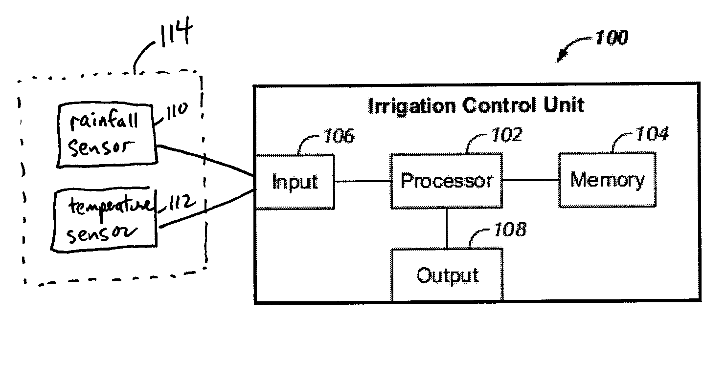
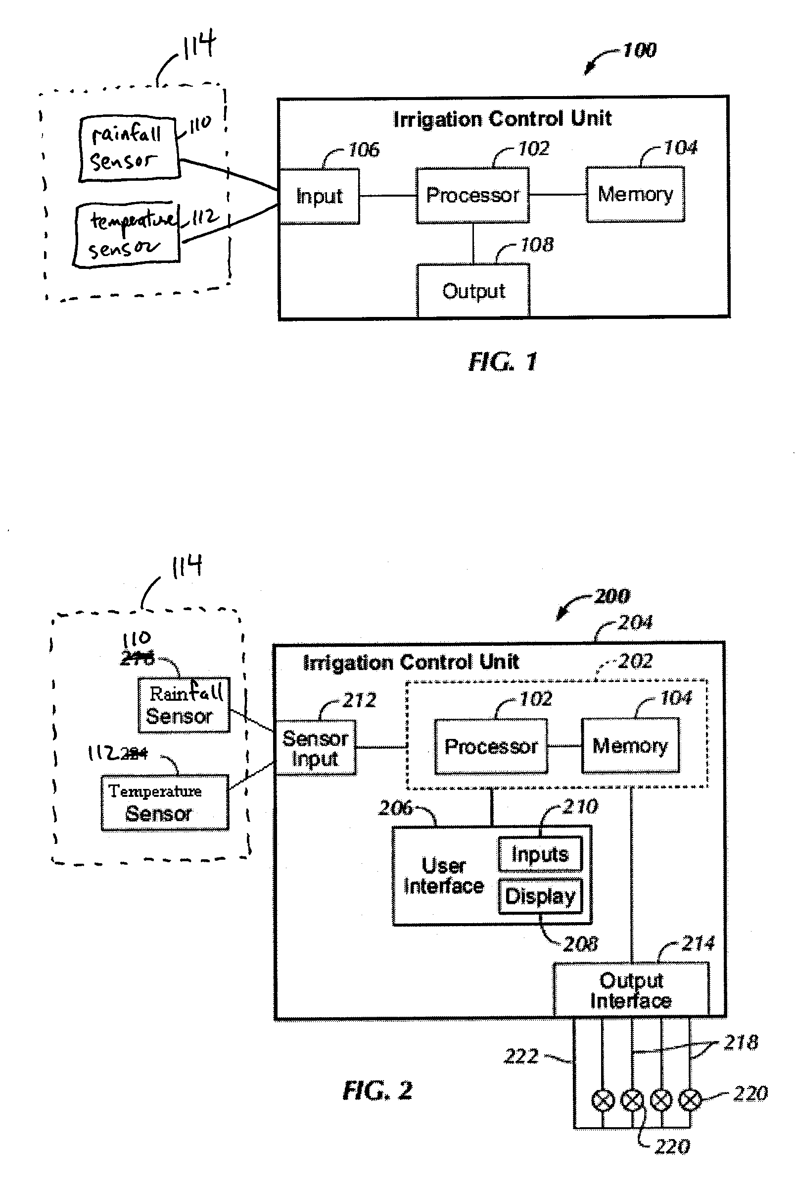
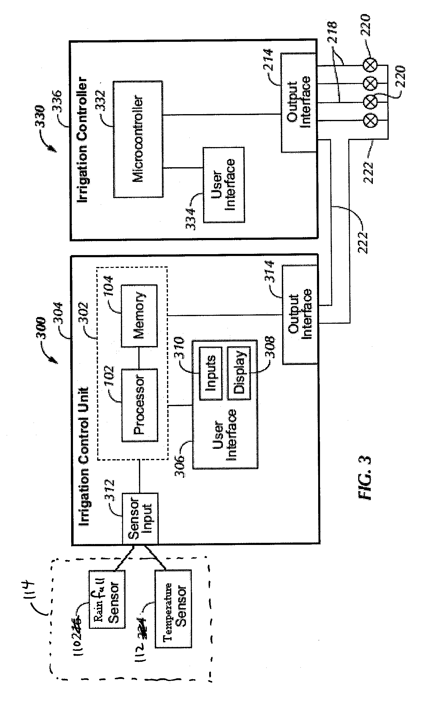
[0006]One embodiment can be characterized as an irrigation control unit comprising at least one input adapted to be coupled to and receive signals from a rainfall sensor and a temperature sensor, the signals corresponding to current values of an amount of rainfall and temperature. The unit also includes a memory storing historical values of a plurality of variables and a processor coupled to the at least one input and the memory. The processor is adapted to determine plant water requirements at least in part by determining an evapotranspiration (ET) value based at least in part on the historical values of the plurality of variables and the current values of the temperature and making an adjustment according to the current value of the amount of rainfall.
[0007]In another embodiment, the invention may be characterized as a method for use in irrigation control, and means for performing the method, the method comprising the steps: receiving current values of an amount of rainfall and a temperature from a rainfall sensor and a temperature sensor, the current values corresponding to a geographic location; receiving stored historical values of a plurality of variables from a memory, the stored historical values corresponding to the geographic region; determining an evapotranspiration (ET) value based on the historical values of the plurality of variables and the current value of the temperature; and determining plant water requirements based at least in part on the ET value and the current value for the amount of rainfall.
[0008]In another embodiment, the invention may be characterized as a method for use in irrigation control comprising the steps: receiving, via a user interface of an irrigation control unit, user entered historical values of one or more environmental variables useful in determining plant water requirements, the user entered historical values corresponding to the geographic region; storing the user entered historical values in a memory; receiving current values of one or more other environmental variables useful in determining the plant water requirements from one or more sensors coupled to the irrigation control unit, the current values corresponding to the geographic region, the one or more other environment variables being different from the one or more environmental variables; storing the current values in the memory; receiving one or more of the user entered historical values of the one or more environmental variables from the memory; receiving one or more of the current values of the one or more other environmental variables from the memory; and determining the plant water requirements based at least in part using the one or more of the user entered historical values of the one or more environmental variables and the one or more of the current values of the one or more other environmental variables.
[0009]In another embodiment, the invention may be characterized as an irrigation control unit comprising: a user interface adapted to receive inputs from a user; a memory adapted to store environmental variables; at least one input adapted to be coupled to and receive signals from one or more sensors; and a processor coupled to the memory and the user interface. The processor is adapted to: receive, via the user interface, user entered historical values of one or more environmental variables useful in determining plant water requirements, the user entered historical values corresponding to the geographic region; store, in the memory, the user entered historical values received from the user interface; receive, via the at least one input, current values of one or more other environmental variables useful in determining the plant water requirements from the one or more sensors, the current values corresponding to the geographic region, the one or more other environment variables being different from the one or more environmental variables; store, in the memory, the current values received from the at least one input; and determine plant water requirements at least in part using one or more of the user entered historical values of the one or more environmental variables and one or more of the current values of the one or more other environmental variables.
[0010]In another embodiment, the invention may be characterized as a method for use in irrigation control comprising the steps: obtaining an irrigation control unit configured and manufactured to determine plant water requirements based at least in part on values of a plurality of environmental variables, the irrigation control unit configured and manufactured to receive current values of a first set of one or more of the plurality of environmental variables, the current values corresponding to a geographic region; determining a historical value of each of a second set of one or more of the plurality of environmental variables, the historical values corresponding to the geographic region, wherein the first set of the one or more of the plurality of environmental variables are different environmental variables that the second set of the one or more of the plurality of environmental variables; and entering, via a user interface of an irrigation control unit, the historical values of each of the second set of the one or more of the plurality of environmental variables to be stored in an irrigation control unit for later use together with the current values of the first set of the one or more of the plurality of environmental variables by the irrigation control unit in determining the plant water requirements.


