Breathing apparatus

a breathing apparatus and self-contained technology, applied in the direction of breathing protection, underwater equipment, waterborne vessels, etc., can solve the problem of toxins diffusing through the membran

Active Publication Date: 2010-06-17
DRAEGER SAFETY UK
View PDF6 Cites 10 Cited by
  • Summary
  • Abstract
  • Description
  • Claims
  • Application Information

AI Technical Summary

Benefits of technology

[0009]Accordingly, a need exists for an LDV and / or LDV / mask combination in which the likelihood of such a build up of toxins on the external face of the diaphragm is minimised or eliminated.

Problems solved by technology

Since the apron of the diaphragm is a thin membrane, typically of rubber or silicone, concerns have been expressed that in exceptional cases if the diaphragm faces this exposure repeatedly or for long periods this could lead to toxins diffusing through the membrane.

Method used


Image

  • Breathing apparatus
  • Breathing apparatus
  • Breathing apparatus

Examples


Embodiment Construction

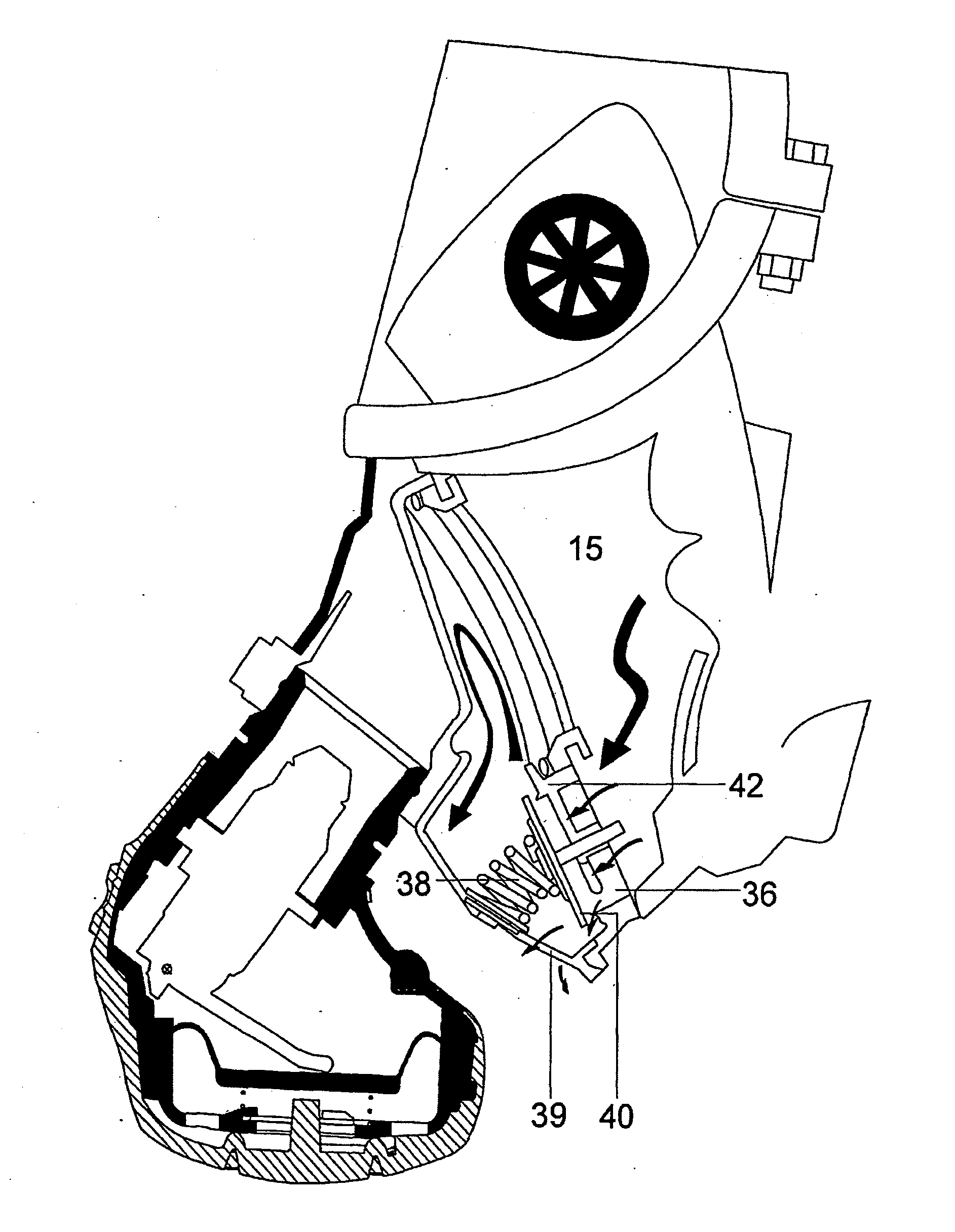
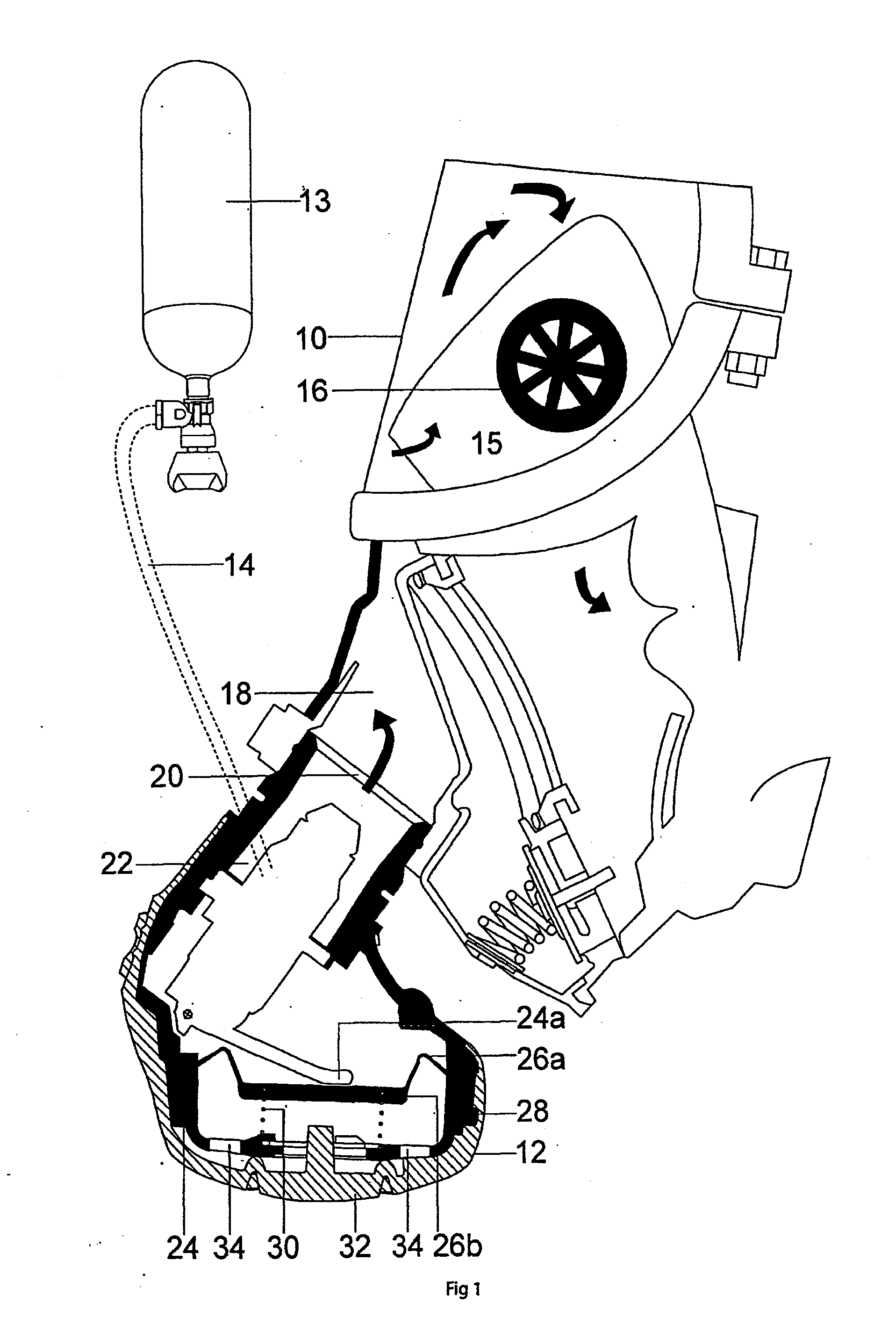
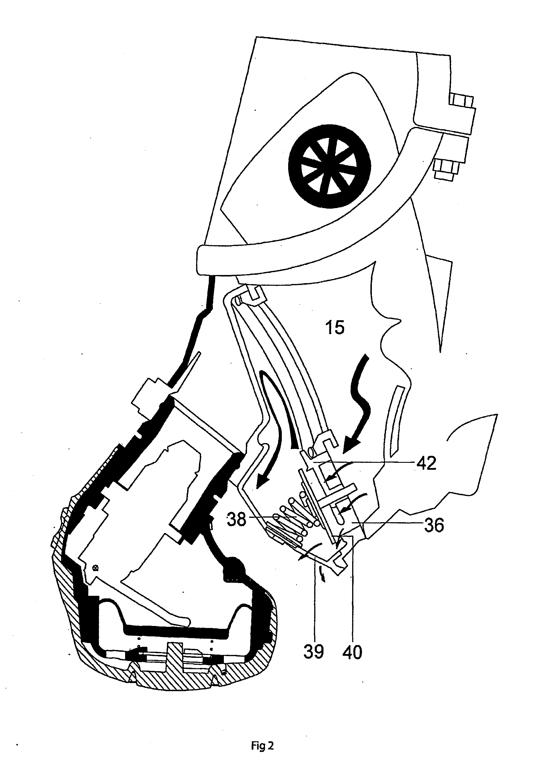
[0026]Turning to FIG. 3, this is a side view of a mask and LDV constructed in accordance with one exemplary preferred embodiment of the present invention. In particular, FIG. 3 shows a mask 10, an LDV, generally represented by 12, a cylinder 13 and hose 14, and an inner mask 15 complete with non-return valve 16. The mask 10, LDV 12 cylinder 13 and hose 14 are identical to the equivalents, shown in FIGS. 1 and 2 and, during an inhalation phase, they operate in the same manner as the prior art apparatus described above.

[0027]However, in accordance with the present invention the LDV 12 is provided with a cover 44 which comprises three parts, namely, a yoke, 44a, a rubber cover portion 44b and a rigid plastic duct portion 44c.

[0028]The rigid plastic yoke 44a extends across the top of the supply port (not shown) of the LDV and is secured by screws 46 (only one of which is shown in FIG. 3). The screws are located on both sides of the yoke and threadedly engage the rigid plastic duct port...


PUM


Abstract

A face mask (10) mechanically coupled to a lung demand valve (LDV) (12). The face mask (10) comprises a main mask and an inner mask (15) which fits over the wearer's mouth and nose. The interior of the inner mask (15) is in fluidic communication with the interior of the main mask (10) by means of non-return valves (16). The interior of the main mask is in fluidic communication with an inlet port (18) which is mechanically and fluidically coupled to a supply port (20) of an LDV. The LDV (12) includes a diaphragm and a cover (44) which comprises three parts (44a, 44b) and (44c). Exhaled air is used to flush the space around the diaphragm. Thus, any toxic or undesirable gas in the vicinity of the diaphragm is pushed out to atmosphere by the exhaled air flowing past and around the diaphragm.

Description

FIELD OF THE INVENTION [0001]The present invention relates to self-contained breathing apparatus (SCBA) and particularly to breathing apparatus utilising a face mask and a second stage regulator, or so-called lung-demand-valve (LDV).[0002]In a SCBA set breathing gas (usually air) is stored at a first, “high” pressure in a pressurized cylinder. From the cylinder the gas is conveyed to the user for breathing via at least one stage of regulator, in which the gas is reduced in pressure. It is preferable to have two stages of regulator each of which reduces the pressure. In such a system the first reduction in pressure takes place, as the gas leaves the cylinder, in a first stage regulator. The gas is stored in the cylinder at a pressure of typically up to 200 to 300 bar and after the first stage of pressure reduction has a pressure in the order of 7.5 bar. The gas is then considered to be at “medium” pressure. The medium pressure gas is then conveyed to a second stage regulator, usually...

Claims


Application Information

Patent Timeline
Patent Type & Authority Applications(United States)
IPC IPC(8): A62B9/02A62B18/10
CPCA62B18/10
Inventor TOWNSEND, PAULHODSON, DAVID
Owner DRAEGER SAFETY UK
Why Eureka
Try Eureka