Base structure of golf club bag

a golf club bag and base technology, applied in the field of golf club bags, can solve the problems of golf club bags placed slantingly, prone to shake, and the conventional foot frame structure still has some drawbacks

Inactive Publication Date: 2010-06-17
HUANG XIAO YA
View PDF8 Cites 8 Cited by
  • Summary
  • Abstract
  • Description
  • Claims
  • Application Information

AI Technical Summary

Benefits of technology

[0007]In view of this, it is therefore an object of the invention to provide a golf club bag, which has a larger contact surface area

Problems solved by technology

However, the conventional foot frame structure still has some drawbacks.
Thus, the golf club bag placed slantingly is not stable enough and often tends to shake.
More particularly, the bag tends to fall down when the wind is strong or when the bag is slightly touched so that the u

Method used


Image

  • Base structure of golf club bag
  • Base structure of golf club bag
  • Base structure of golf club bag

Examples


Embodiment Construction

[0021]The present invention will be apparent from the following detailed description, which proceeds with reference to the accompanying drawings, wherein the same references relate to the same elements.

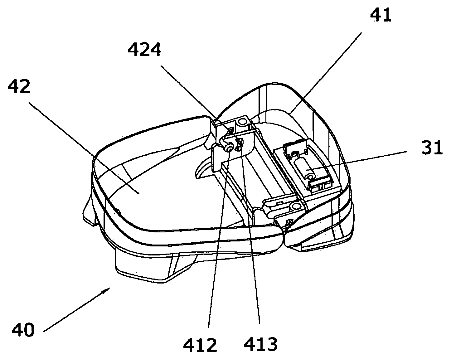
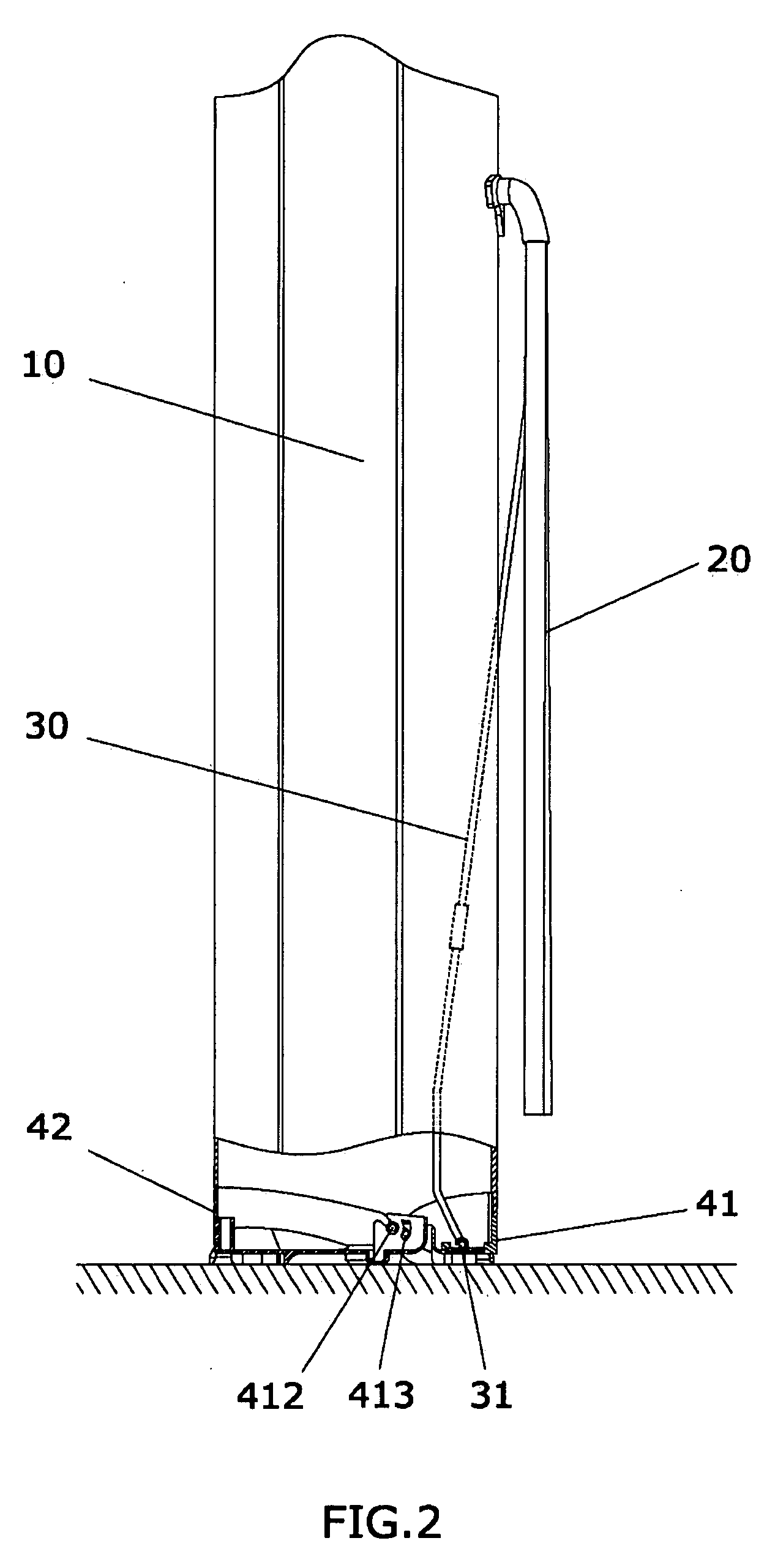
[0022]FIGS. 2 to 5 show the embodied structure according to the preferred embodiment of the invention. Referring to FIGS. 2 to 5, a golf club bag includes a bag body 10, a main support rod 20, a linking rod 30 and a base 40. The bag body 10 is fixed to the base 40. The top end of the main support rod 20 is pivotally connected to the vicinity of a frame opening of the bag body 10. The top end of the linking rod 30 is pivotally connected to the middle-upper portion of the main support rod 20. The bottom end of the linking rod 30 is pivotally connected to the base 40.

[0023]The base 40 is composed of a front base 41 and a rear base 42, which have the substantially the same width and are pivotally connected to each other. A periphery of a bottom end of the bag body 10 is simultaneously sew...


PUM


Abstract

A golf club bag includes a bag body, a main support rod, a linking rod and a base. The bag body is fixed to the base composed of a front base and a rear base, which have substantially the same width and are pivotally connected to each other. When the bag body is placed slantingly, the front base may serve as a main supporting member at a bottom portion thereof, the larger supporting surface area can be obtained, and the stability of placement can be enhanced. In addition, peripheries of the front base and the rear base are connected to the bag body, a bottom end of the linking rod is inserted into the bag body and pivotally connected to the front base. Thus, it is possible to prevent its pivotal connection portion from being exposed outside the bag body and from being collided and damaged.

Description

BACKGROUND OF THE INVENTION[0001](1) Field of the Invention[0002]The invention relates to a golf club bag, and more particularly to a golf club bag having a base, which can provide a stable and reliable support when the golf club bag is placed slantingly.[0003](2) Description of the Prior Art[0004]As well known in the art, a golf club bag is used so that the user can house and carry golf clubs conveniently. At present, most golf bags can be placed upright and slantingly to provide the best angle for the users to get the golf clubs.[0005]Usually, a foot frame that may be freely retracted and expanded is placed outside the golf bag so that the bag can be placed slantingly. As shown in FIG. 1, the currently available foot frame structure usually includes a main support rod 20′, a linking rod 30′, a base 40′ and a turning plate 50′. A bag body 10′ is fixed to the base 40′. The turning plate 50′ is fixed to the front bottom surface of the base 40′. The top end of the main support rod 20′...

Claims


Application Information

Patent Timeline
IPC IPC(8): A63B55/06A63B55/57
CPCA63B55/045A63B55/57A63B55/53
Inventor HUANG, XIAO-YA
Owner HUANG XIAO YA
Why Eureka
Try Eureka