This helps you quickly interpret patents by identifying the three key elements:
Problems solved by technology
Method used
Benefits of technology
Benefits of technology
[0007]The present invention has been accomplished under the circumstances in view. According to one aspect of the present invention, the cooler device comprises a metal base member, and a plurality of metal radiation fins mounted on the metal base member. The metal radiation fins each have at least one backwardly curved and crimped bottom mounting portion. The metal base member has a plurality of deep locating grooves, which receive the backwardly curved and crimped bottom mounting portions of the radiation fins; the metal base member is compressed to fixedly secure the backwardly curved and crimped bottom mounting portions of the radiation fins to the metal base member. Therefore, the radiation fins are quickly and easily affixed to the base member without electroplating or the use of solder paste or bonding means, i.e., the mounting procedure of the present invention is environmentally friendly.
[0008]According to another aspect of the present invention, each radiation fin has a plurality of backwardly curved and crimped bottom mounting portions respectively fastened to the base member. Therefore, the thickness of the bottom side of each radiation fin is relatively increased, i.e., the contact surface area between the radiation fins and the base member is relatively increased for quick transmission of heat energy from the base member to the radiation fins.
[0010]According to still another aspect of the present invention, each radiation fin has the bottom side turned backwards and crimped, therefore the bottom mounting side of each radiation fin has a certain wall thickness, and the base member can be directly extruded from aluminum or copper to provide the matching locating grooves for the mounting of the backwardly curved and crimped mounting portions of the radiation fins quickly and efficiently without a secondary processing.
Problems solved by technology
The use of a solder paste or bonding agent or the application of a nickel-plating procedure greatly increases the manufacturing cost of the heat sink.
However, the secondary processing of the base member greatly increases the cost.
Further, the limited contact surface area between the base member and the radiation fins does not allow quick transmission of heat energy from the base member to the radiation fins for quick dissipation.
Method used
Image
Click on the blue label to locate the original text in one second.
Reading with bidirectional positioning of images and text.
Examples
first embodiment
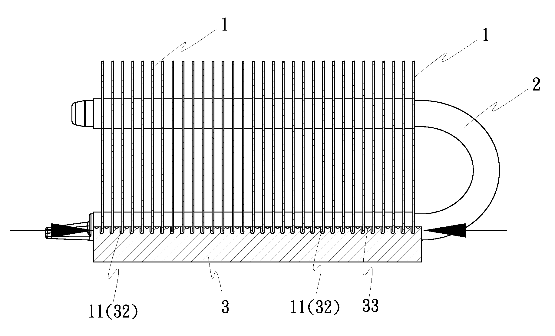
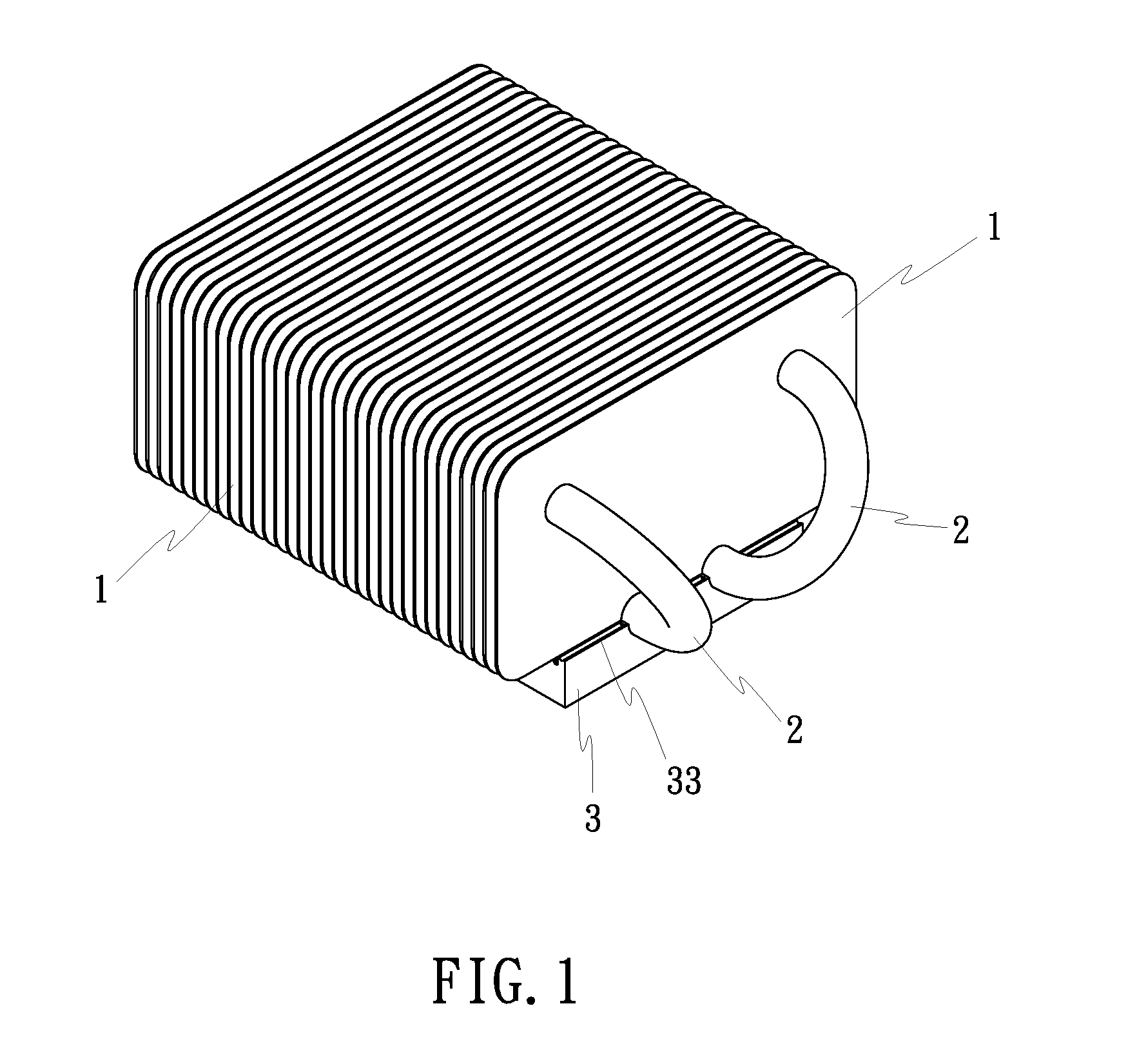
[0029]Referring to FIGS. 1˜5, a cooler device in accordance with the present invention is shown comprised of a set of radiation fins 1, a plurality of heat tubes 2, and a base member 3.
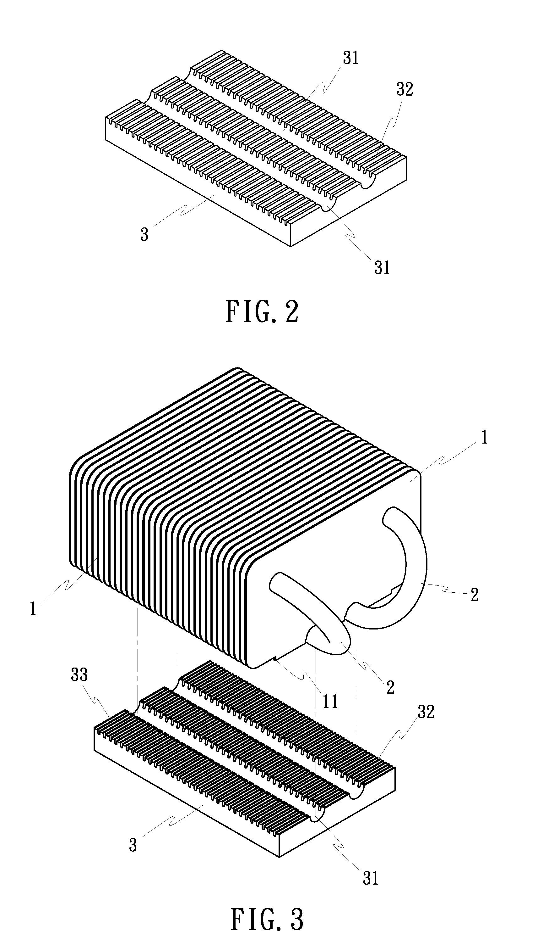
[0030]The radiation fins 1 have same or different shapes, and are arranged in parallel. Further, each radiation fin 1 has a plurality of backwardly curved and crimped bottom mounting portion 11 (see FIGS. 4 and 5).
[0031]The heat tubes 2 are double closed-end U-tubes filed with a working fluid (not shown) and fixedly fastened to the radiation fins 1 to keep the radiation fins 1 in parallel.
[0032]The base member 3 is a solid flat metal block extruded from aluminum or copper, having two longitudinal positioning grooves 31 (of semicircular cross section) formed on the top wall and respectively fitting under the periphery of a part of each of the heat tubes 2, a plurality of deep transverse locating grooves 32 formed on the top wall and adapted to receive the backwardly curved and crimped bottom mounting p...
second embodiment
[0034]FIGS. 6 and 7 show a cooler device in accordance with the present invention. According to this design, the cooler device is comprised of a set of radiation fins 1, and a base member 3.
[0035]The radiation fins 1 each have a plurality of hooked portions 12 protruded from one side, namely, the top side, and a plurality of backwardly curved and crimped bottom mounting portions 11. Further, the radiation fins 1 are flat metal sheet members of same or different contours. By means of hooking the hooked portions 12 of one radiation fin 1 to another, the radiation fins 1 are fastened together in a parallel manner.
[0036]The base member 3 is a solid flat metal block extruded from aluminum or copper, having a plurality of deep transverse locating grooves 32 formed on the top wall and adapted to receive the backwardly curved and crimped bottom mounting portions 11 of the radiation fins 1, and a plurality of shadow transverse grooves 33 formed on the top wall between each two adjacent trans...
third embodiment
[0040]FIG. 16 shows a cooler device in accordance with the present invention. According to this embodiment, the cooler device is comprised of a base member 3a and a plurality of radiation fins 1. The base member 3a is a metal cylinder having a plurality of deep transverse mounting grooves extending along the length and alternatively arranged in parallel around the periphery. The backwardly curved and crimped bottom mounting portions (not shown) of the radiation fins 1 are respectively fastened to the deep transverse mounting grooves of the base member 3a.
PUM
Abstract
A cooler device includes a metal base member and a plurality of metalradiation fins. The metal base member has parallel locating grooves; the metal radiation fins are fastened to one another in a stack by respective hooked portions thereof or by means of closed-end heat tubes, the metal radiation fins each having backwardly curved and crimped bottom mounting portions respectively fitted into the locating grooves of the metal base and fixedly secured thereto by means of compacting the locating grooves of the metal base member without electroplating or using solder paste or bonding means.
Description
BACKGROUND OF THE INVENTION[0001](a) Field of the Invention[0002]The present invention relates to a cooler device and more particularly to the mounting arrangement of the metal base member and metal radiation fins of a cooler device, which greatly increases the contact surface area between the metal base member and the metal radiation fins and is environmentally friendly.[0003](b) Description of the Prior Art[0004]Conventional heat sinks are commonly comprised of a base member and a plurality of radiation fins arranged in parallel on the metal base member. The base member and the radiation fins are generally extruded from aluminum or copper. Therefore, the base member of a conventional heat sink is called the aluminum base or copper base. Further, regular heat sinks include heat sinks with heat tubes and heat sinks without heat tube. In a heat sink without heat tube, the radiation fins are arranged in parallel and fastened to one another by respective hooked portions thereof. In a h...
Claims
Application Information
Patent Timeline
Application Date:The date an application was filed.
Publication Date:The date a patent or application was officially published.
First Publication Date:The earliest publication date of a patent with the same application number.
Issue Date:Publication date of the patent grant document.
PCT Entry Date:The Entry date of PCT National Phase.
Estimated Expiry Date:The statutory expiry date of a patent right according to the Patent Law, and it is the longest term of protection that the patent right can achieve without the termination of the patent right due to other reasons(Term extension factor has been taken into account ).
Invalid Date:Actual expiry date is based on effective date or publication date of legal transaction data of invalid patent.

