
Distributed energy services management system

Active Publication Date: 2013-06-27
SUNVERGE ENERGY
View PDF6 Cites 70 Cited by
  • Summary
  • Abstract
  • Description
  • Claims
  • Application Information

AI Technical Summary

Benefits of technology

The patent describes a system that can assign resources, such as a battery, to different programs. This allows each program to have its own separate portion of the resource, while still being controlled by overall system policies. The system can adapt to real-time changes and events at the remote site, avoiding overlapping or conflicting actions. The system also uses virtual devices that can be controlled by different programs, based on their specific needs and timelines. The technical effect of this patent is a more efficient and responsive system that is able to make decisions and control actions at the remote site without relying on a central control architecture.

Problems solved by technology

These technologies are herein referred to as “distributed energy sources.” Distributed energy sources have been deployed only to a very limited extent for reasons of cost, convenience, and a lack of harmonized grid inter-connection standards.
As a result, residential and commercial power storage and supply devices are typically very large and cumbersome.
Unfortunately, the use of alternative energy sources in conjunction with such power storage and supply device systems has been limited primarily because of cost and convenience and communications standards.

Method used


Image

  • Distributed energy services management system
  • Distributed energy services management system
  • Distributed energy services management system

Examples


Embodiment Construction

[0025]In the following description, for purposes of explanation, numerous specific details are set forth in order to provide a thorough understanding of the various embodiments. It will be evident, however, to one of ordinary skill in the art that the various embodiments may be practiced without these specific details.

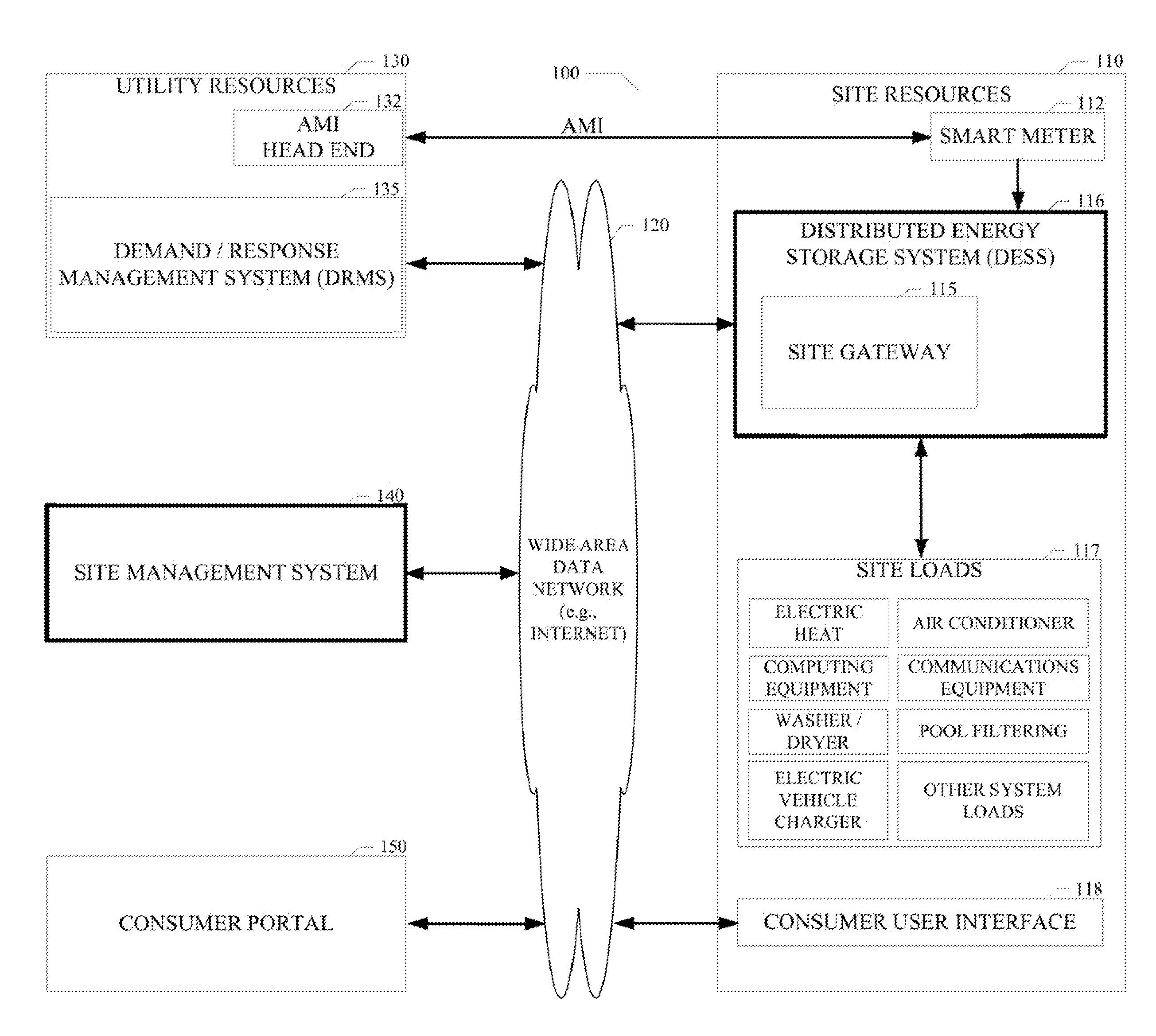
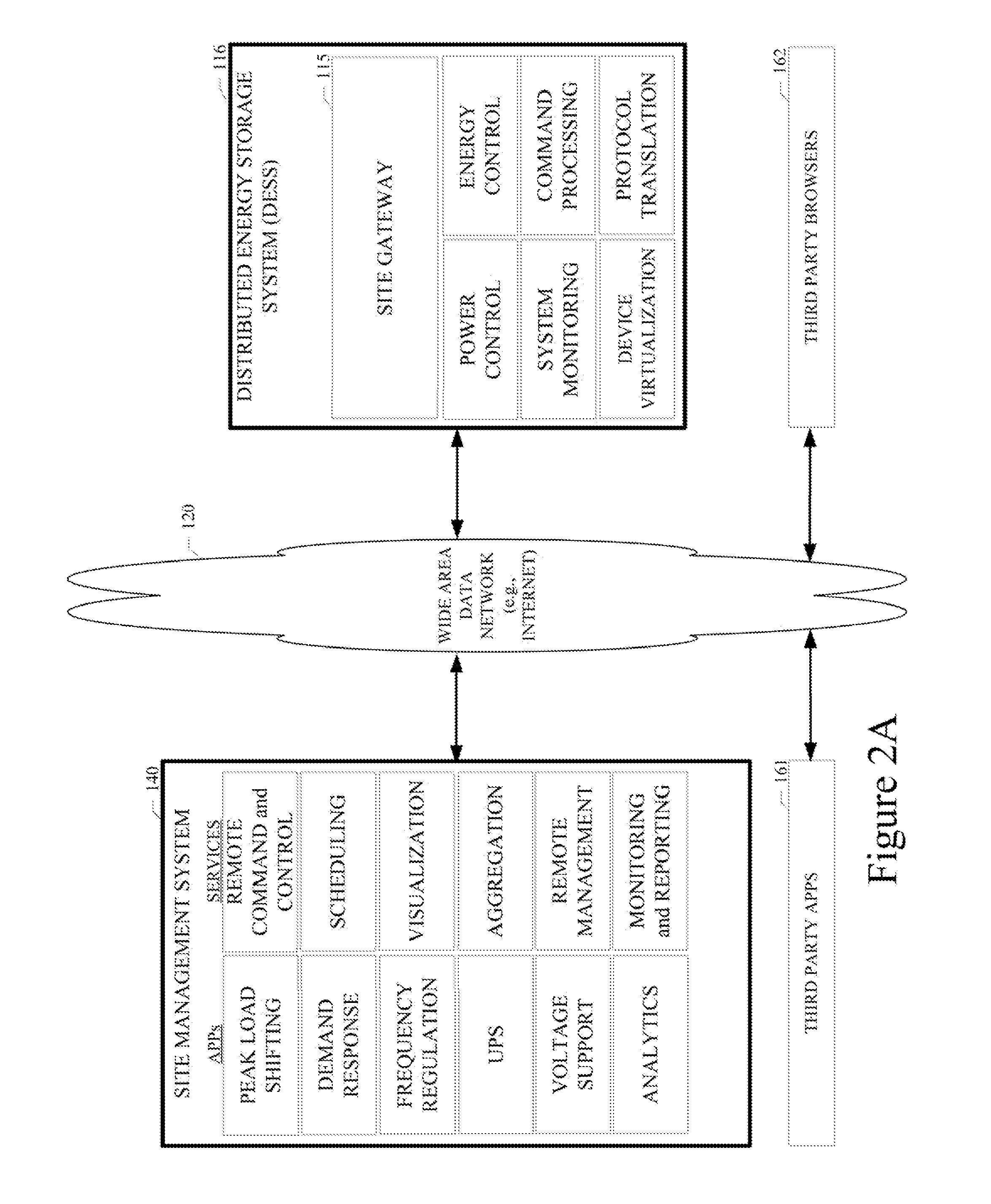
[0026]As described in various example embodiments, systems and methods for distributed energy services management are described herein. In one particular embodiment, the distributed energy services management system is applied in an energy network, such as the systems illustrated in FIGS. 1 through 3. However, it will be apparent to those of ordinary skill in the art that the distributed energy services management techniques described and claimed herein can be used in a variety of other applications and systems.

[0027]The various embodiments disclosed herein provide a solution for cost-effective grid-scale energy storage, generation, and management. The various embodime...


PUM


Abstract

Systems and methods for distributed energy services management are disclosed. A particular embodiment includes: receiving an input command via a network interface at a site gateway, the input command including information for controlling one or more physical devices at a site; converting, by use of a data processor, the input command to a virtualized command in a common command format; executing, by use of the data processor, one or more executor modules to cause execution of one or more corresponding virtual devices associated with the virtualized command; and using the executed one or more virtual devices to control the corresponding one or more physical devices at the site.

Description

PRIORITY PATENT APPLICATION[0001]This is a continuation-in-part patent application of co-pending U.S. patent application Ser. No. 13 / 016,901; filed Jan. 28, 2011; and titled, “Systems, Apparatus, and Methods of a Solar Energy Grid Integrated System with Energy Storage Appliance” by the same applicant. This present patent application draws priority from the referenced patent application. The entire disclosure of the referenced patent application is considered part of the disclosure of the present application and is hereby incorporated by reference herein in its entirety.COPYRIGHT NOTICE[0002]A portion of the disclosure of this patent document contains material that is subject to copyright protection. The copyright owner has no objection to the facsimile reproduction by anyone of the patent document or the patent disclosure, as it appears in the U.S. Patent and Trademark Office patent files or records, but otherwise reserves all copyright rights whatsoever. The following notice applie...

Claims


Application Information

Patent Timeline
IPC IPC(8): G05B11/01
CPCG05B11/01G05B15/02
Inventor SANDERS, DEANSTATMAN, STUART
Owner SUNVERGE ENERGY
Learn More