

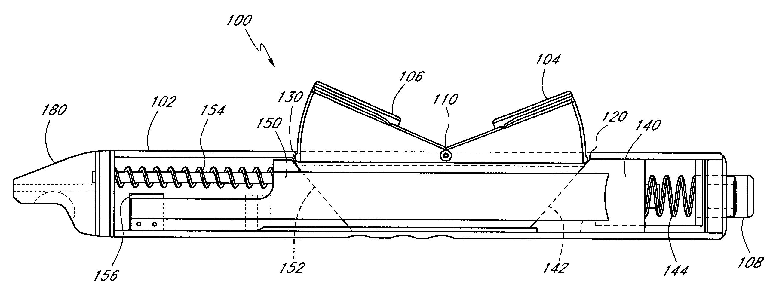
Handle for suturing apparatus
a suction device and hand-held technology, applied in the field of suction devices, can solve the problems of thrombosis, thrombosis bursting, and thrombosis bursting, and achieve the effects of reducing complications and costs, simple operation, and quick and efficient operation
- Summary
- Abstract
- Description
- Claims
- Application Information
AI Technical Summary
Benefits of technology
Problems solved by technology
Method used
Image

Examples
Embodiment Construction
[0057]The preferred embodiments of the present invention described below relate particularly to closing incisions within biological tissue. While the description sets forth various embodiments and specific details, it will be appreciated that the description is illustrative only and should not to be construed in any way as limiting the invention. Furthermore, various applications of the invention, and modifications thereof, which may occur to those skilled in the art, are also encompassed by the general concepts described below.
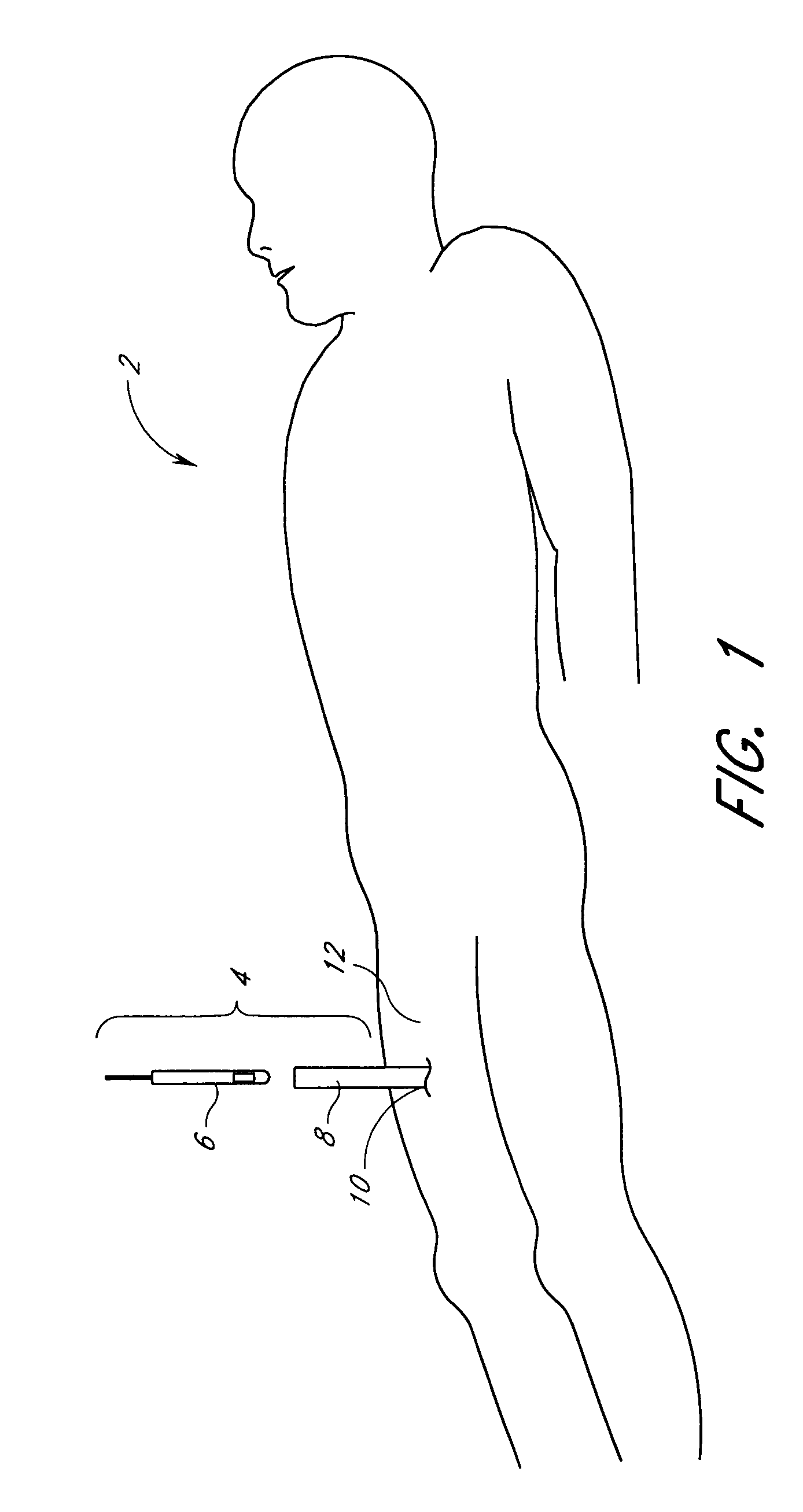
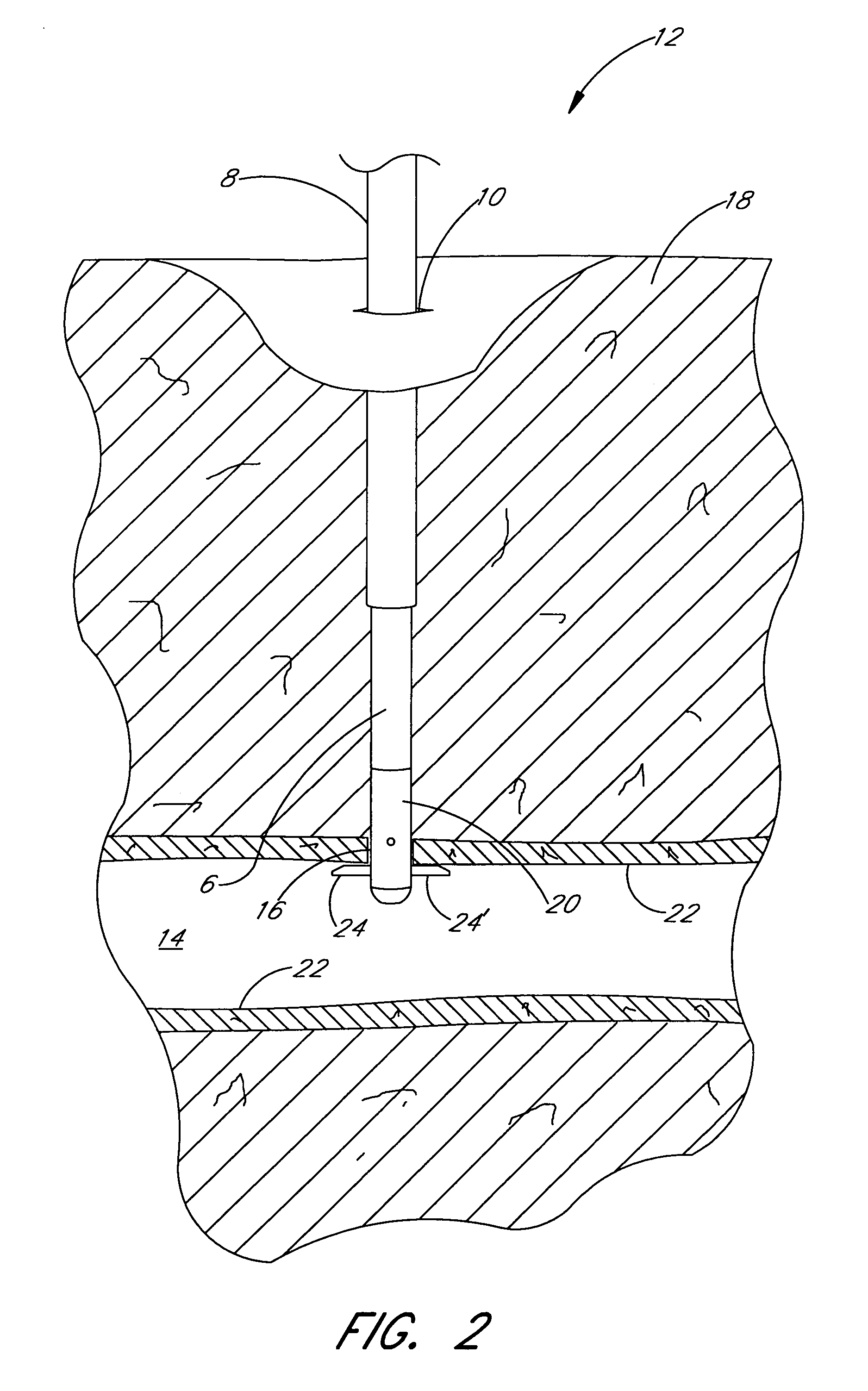
[0058]With reference now to FIG. 1, one preferred assembly 4 for closing an incision is illustrated in an exemplifying use environment. The assembly 4 generally comprises a suturing apparatus 6 and a catheter sheath introducer (CSI) 8. The suturing apparatus 6 may be used to seal a blood vessel following an interventional catheterization procedure, such as an angiogram, angioplasty or other procedure. With reference now to FIG. 2, an enlarged view of the trea...
PUM
 Abstract
Description
Claims
Application Information