Heat pipe assembly

a technology of heat pipe and supporting member, which is applied in the direction of indirect heat exchangers, lighting and heating apparatus, etc., can solve the problems of obstructing the flow of working fluid, insufficient self-support, and complex shape of the supporting member, so as to achieve the effect of simple present invention and easy increase of contact surface area

Inactive Publication Date: 2006-07-27
HSU HUL CHUN
View PDF10 Cites 25 Cited by
  • Summary
  • Abstract
  • Description
  • Claims
  • Application Information

AI Technical Summary

Benefits of technology

[0005] The present invention is to provide a heat pipe assembly, which includes a supporting member composed of a plurality of radially and axially arrange stripes that are mutually stacked. In this manner, mutually communicable working fluid channels are formed in the flattened portion of the heat pipe. Since the structure of the present invention is quite simple, one can easily increase the contact surface area when the flattened heat pipe is combined with a cooling element or a heat source.

Problems solved by technology

When the wick structure is made of metallic web, there is insufficient self-support so as to be attached to the inner surface of the pipe body.
In particular, the wick structure adjacent the flattened portion is easily disengaged or dismantled when the heat pipe assembly needs to be flattened in order to increase the contact surface area with the cooling element or the heat source, thereby obstructing the flow of the working fluid.
However, the shape of the supporting member is often very complicated.
In addition, the supporting member can not be disposed before the heat pipe assembly is flattened.
Therefore, an independent manufacturing process is required, which renders the fabrication costly and disadvantageous for mass production.

Method used


Image

  • Heat pipe assembly
  • Heat pipe assembly
  • Heat pipe assembly

Examples


Embodiment Construction

[0016] In order to better understanding the features and technical contents of the present invention, the present invention is hereinafter described in detail by incorporating with the accompanying drawings. However, the accompanying drawings are only for the convenience of illustration and description, no limitation is intended thereto.

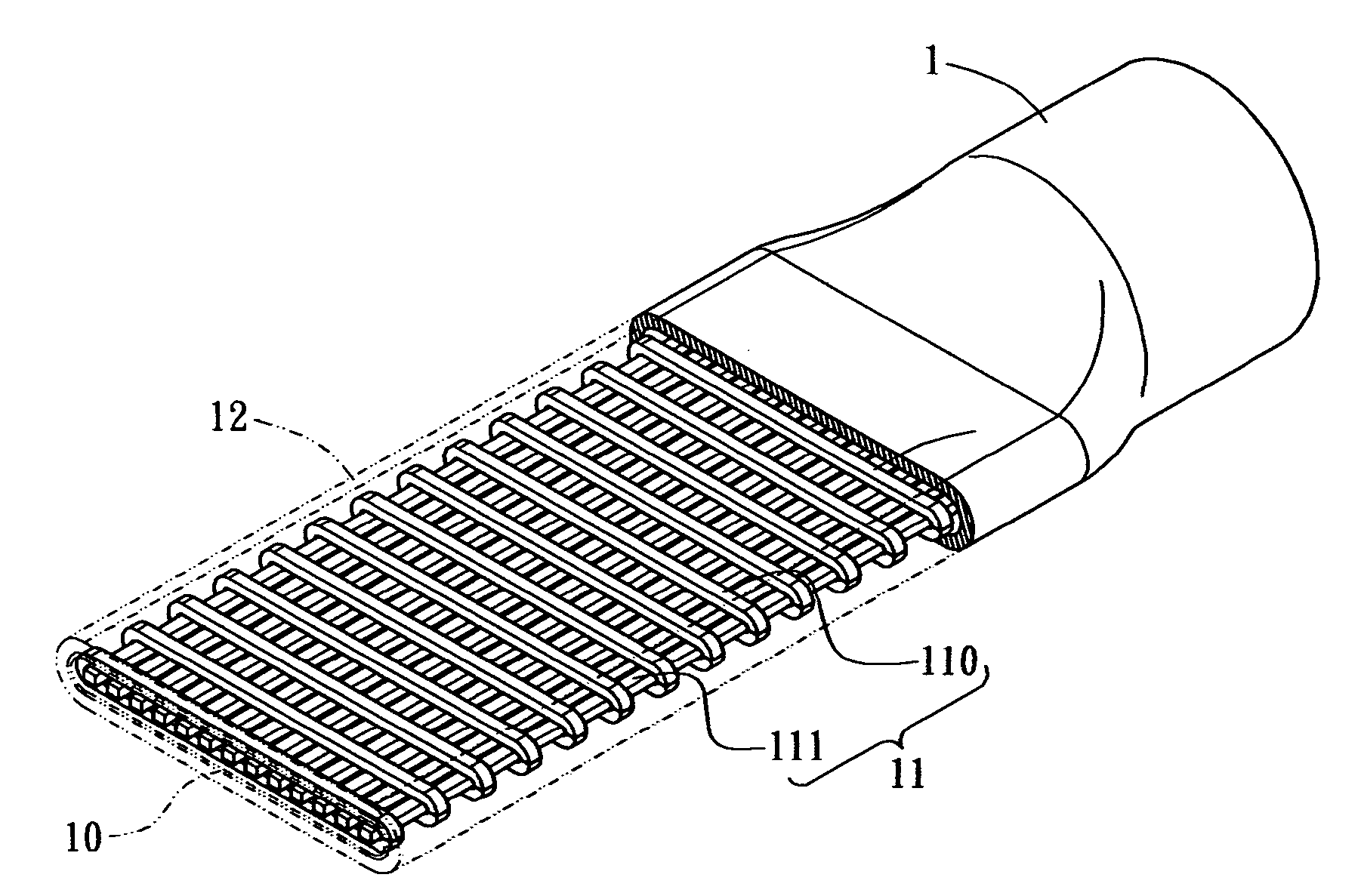
[0017] Referring first to FIG. 9, the heat pipe assembly of the present invention in use is illustrated. The heat pipe assembly of the present invention includes a heat pipe 1 having at least a flattened portion 12 so as to contact the heat transfer base 2 with a larger contact surface area. The other end of the heat pipe 1 can still connect with a plurality of cooling fins 3 for satisfying the cooling needs.

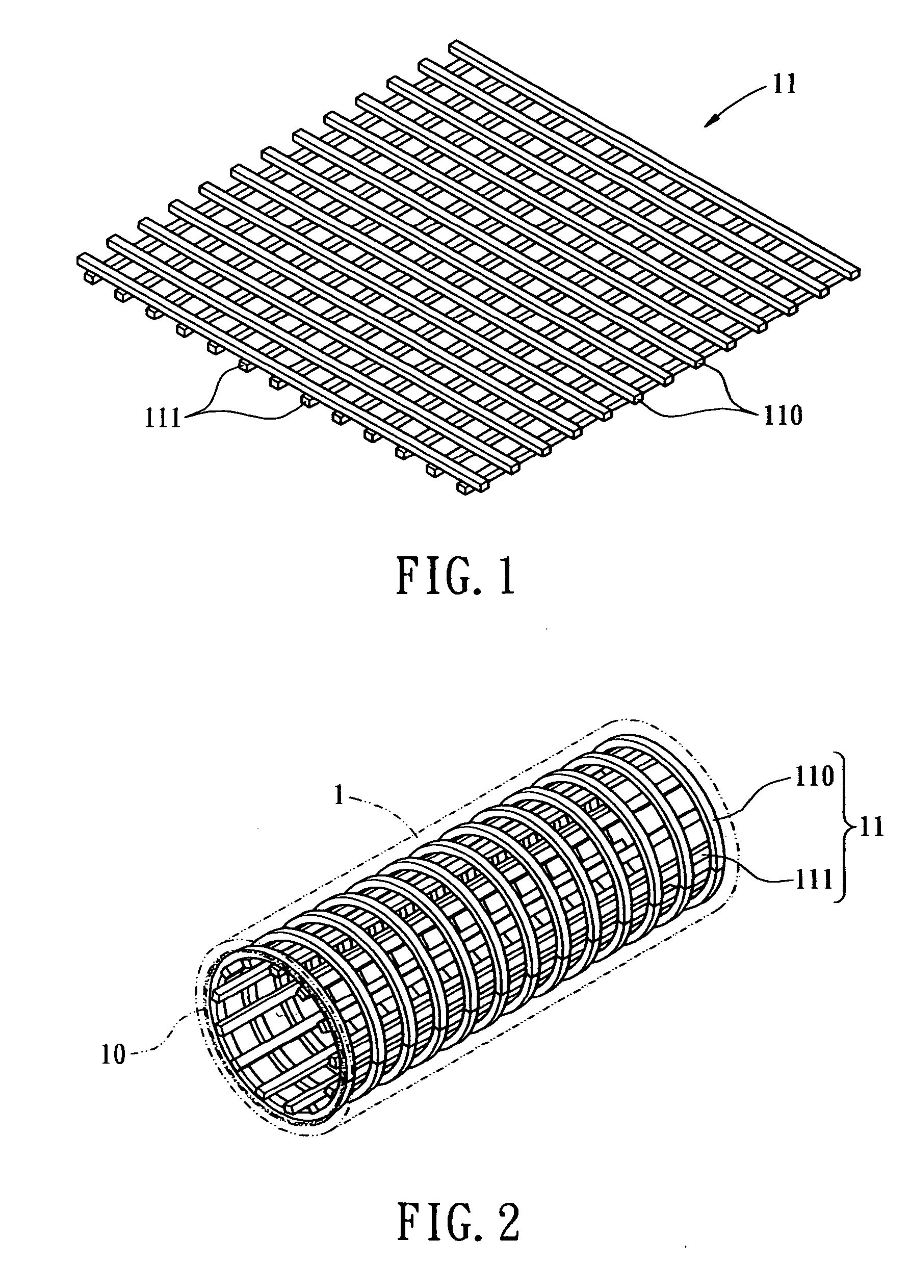
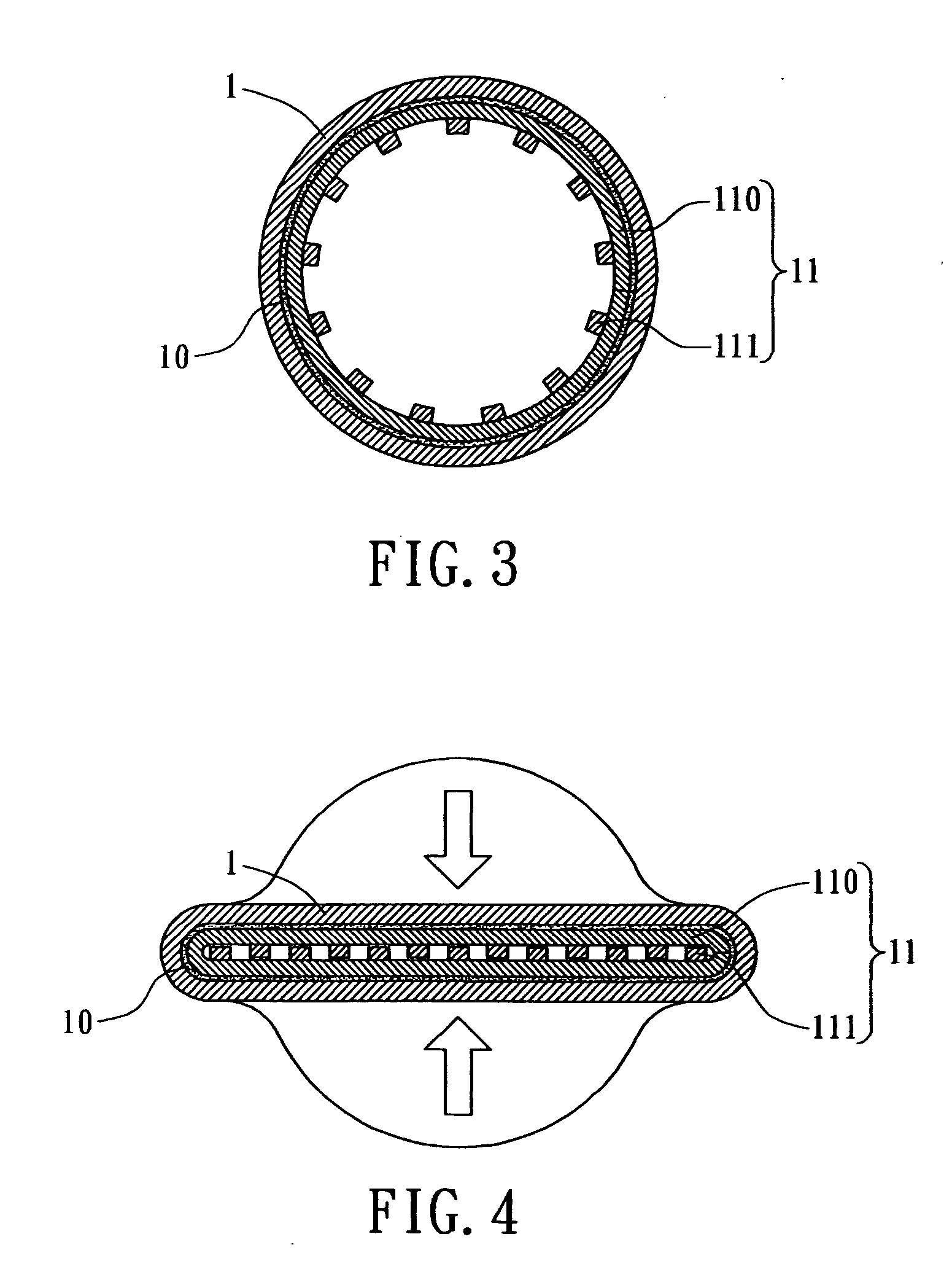
[0018] As shown in FIG. 4 and FIG. 5, the flattened portion 12 of the heat pipe 1 is flattened from the cylindrical pipe body. As shown in FIG. 2 and FIG. 3, the flattened portion 12 is a hollow cylinder like the other portion of the heat pipe ...


PUM


Abstract

A heat pipe assembly includes at least a flattened portion formed on the heat pipe. The internal surface of the heat pipe includes a wick structure attached thereon, and a mesh supporting member disposed therein. The wick structure is compressed on the internal surface of the heat pipe by using the mesh supporting member. The mesh supporting member includes a plurality of radially and axially arranged stripes. The radially and axially arranged stripes are orthogonally stacked, thereby forming mutually communicable working fluid channels in the flattened portion of the heat pipe.

Description

BACKGROUND OF THE INVENTION [0001] The present invention relates generally to a heat pipe assembly, and more particularly to a heat pipe assembly having a flattened portion that is composed of vertically and horizontally arranged working fluid channels. [0002] There are innumerable heat transfer elements or devices currently available in the commercial market. Among them, heat pipe assemblies are often adapted for satisfying the cooling and heat transfer needs. The basic structure of a heat pipe assembly includes a pipe body and a wick structure attached to the inner surface of the pipe body. The heat from the heat source is then transferred to a working fluid via the capillary phenomena of the wick structure. The working fluid is then vaporized. The working fluid vapor is afterwards condensed into liquid state and returned to the heat point. By performing such a continuous thermal circle of absorbing and dissipating heat, one can achieve the cooling purpose by using the heat pipe a...

Claims


Application Information

Patent Timeline
Patent Type & Authority Applications(United States)
IPC IPC(8): F28D15/02
CPCF28D15/0233F28D15/046
Inventor HSU, HUL-CHUN
Owner HSU HUL CHUN
Why Eureka
Try Eureka