Eureka AIR delivers breakthrough ideas for toughest innovation challenges, trusted by R&D personnel around the world.

Cushion for aircraft ejection seat

Active Publication Date: 2010-06-17
AMI INDS
View PDF12 Cites 7 Cited by
  • Summary
  • Abstract
  • Description
  • Claims
  • Application Information

AI Technical Summary

Benefits of technology

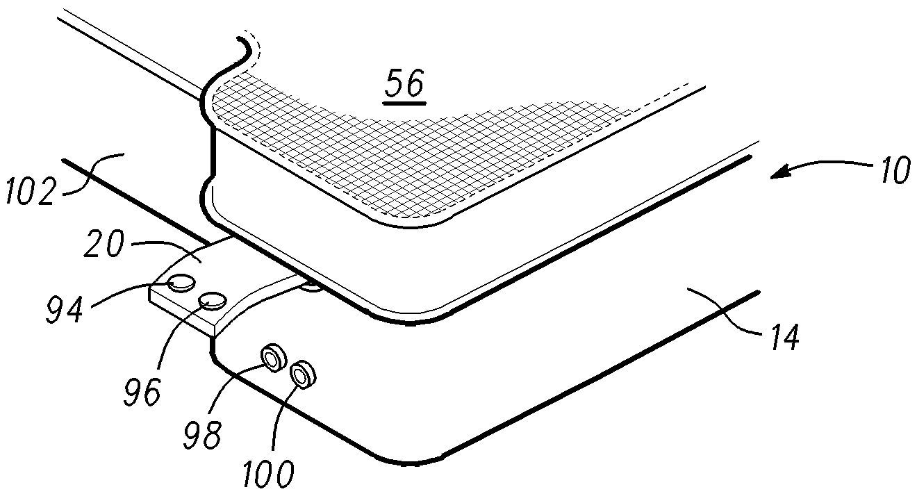
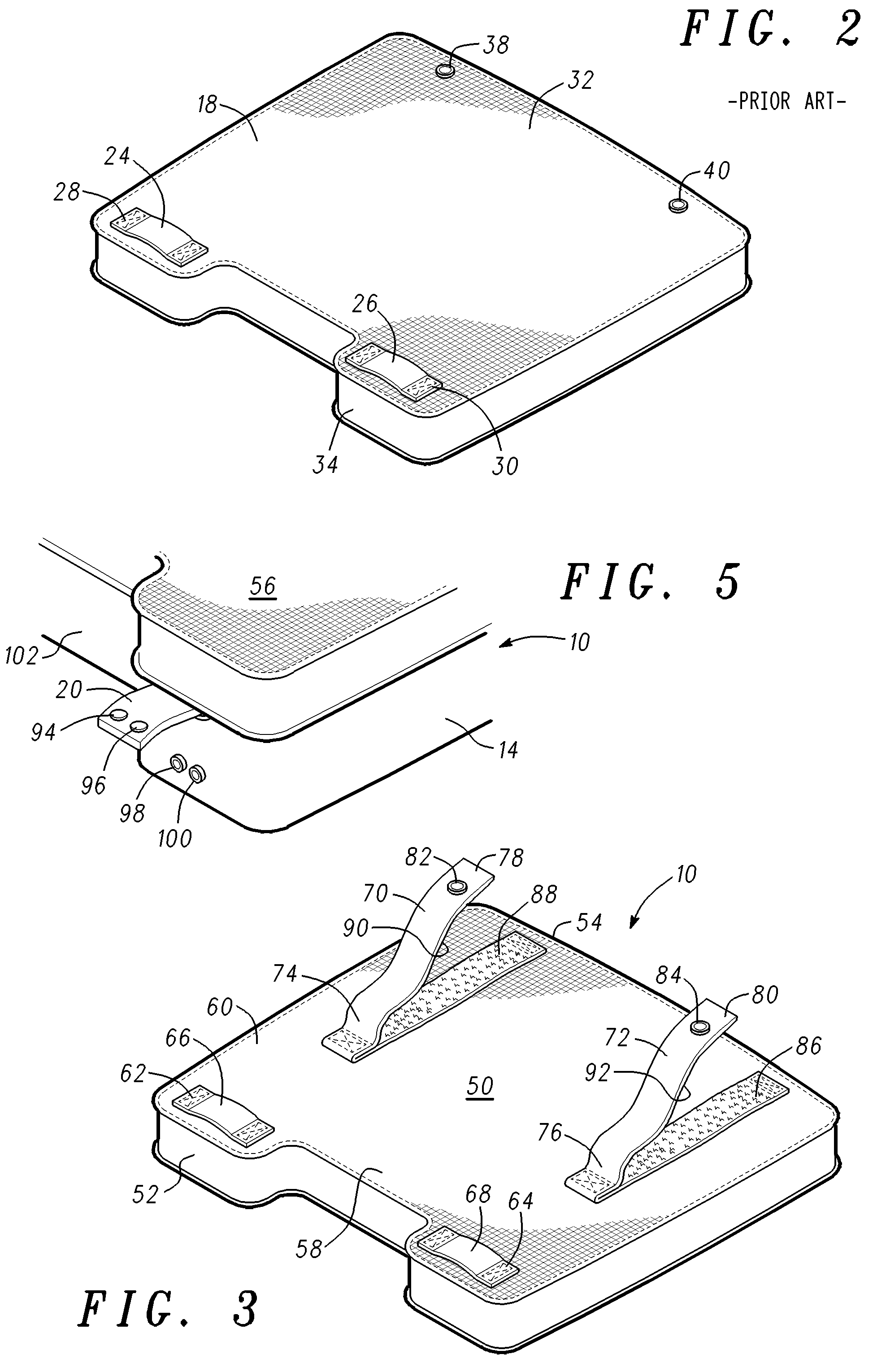
[0006]The present invention comprises a seat cushion for an aircraft seat, in particular an aircraft ejection seat. Accordingly to an embodiment of the invention, the seat cushion includes a plurality of rear edge securing straps attached to the lower surface of the seat cushion. The rear edge securing straps each have a free end that includes a pull-the-dot fastener that engages a corresponding pull-the-dot fastener at the rear edge of the seat pan. The length of the rear edge securing straps is selected so that when the seat cushion is installed, the rear edge securing straps are substantially taut so that the seat cushion is firmly held in place. The seat cushion is easily removable because the pull-the-dot fasteners are at the ends of the rear edge securing straps rather than affixed directly to the bottom of the seat cushion. Therefore, when the front edge of the seat cushion is released, the seat cushion can be lifted up enough to allow the maintenance crewmember's hand to slide underneath the cushion to release the pull-the-dot fastener without pulling at the bottom of the seat cushion. Hook and loop fasteners may be disposed between the upper surface of the rear edge securing straps and the bottom surface of the cushion for additional resistance to shifting when installed.

Problems solved by technology

Although the prior art ejection seat cushion adequately withstands the rigors of military service, cushions are often damaged during maintenance because of the stiffness of the seat cushion and the close proximity of the rear pull-the-dot fasteners to the seat back.
It is difficult for a maintenance crewmember to work his / her fingers between the seat cushion and seat back to release the pull-the-dot fasteners.
Consequently, the seat cushion is often pulled on directly, with the result that the pull-the-dot fasteners tear from the seat cushion rather than releasing from the seat pan.

Method used


Image

  • Cushion for aircraft ejection seat
  • Cushion for aircraft ejection seat
  • Cushion for aircraft ejection seat

Examples


Embodiment Construction

[0014]The drawing figures are intended to illustrate the general manner of construction and are not necessarily to scale. In the detailed description and in the drawing figures, specific illustrative examples are shown and herein described in detail. It should be understood, however, that the drawing figures and detailed description are not intended to limit the invention to the particular form disclosed, but are merely illustrative and intended to teach one of ordinary skill how to make and / or use the invention claimed herein and for setting forth the best mode for carrying out the invention.

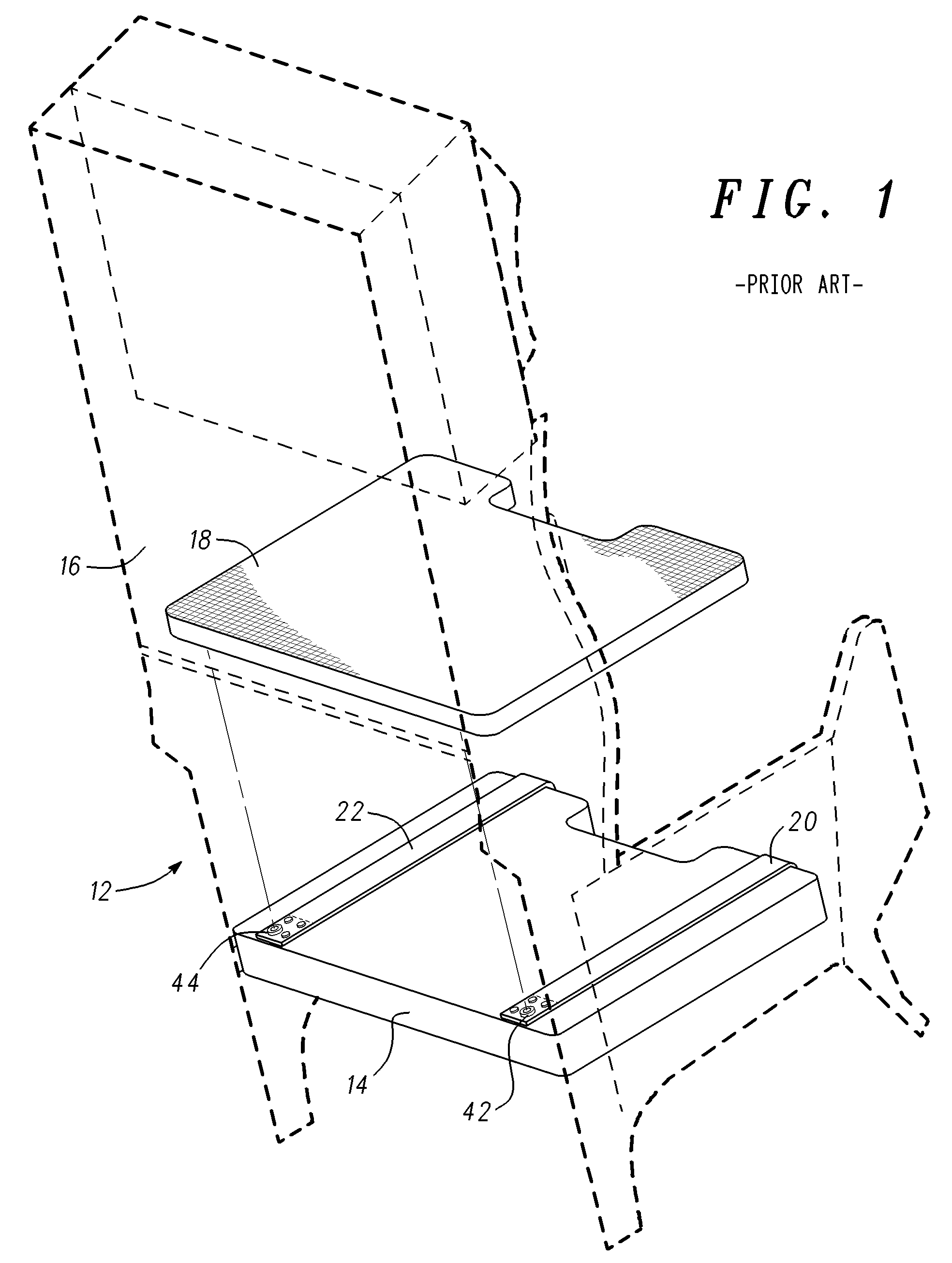
[0015]With reference to FIGS. 1 and 2, a prior art ejection seat 12 comprises a rigid seat pan 14 and a rigid seatback 16. Ejection seat 12 may be any aircraft ejection seat but in the illustration of FIG. 1 comprises an ACES II® ejection seat found in United States Airforce F-15, F-16 and other combat aircraft. Ejection seat 12 is equipped with a seat cushion 18 which is attached to seat pan 1...


PUM


Abstract

A seat cushion for an aircraft seat includes a plurality of rear edge securing straps attached to the lower surface of the seat cushion. The rear edge securing straps each have a free end that includes a pull-the-dot fastener that engages a corresponding pull-the-dot fastener at the rear edge of the seat pan. The length of the rear edge securing straps is selected so that when the seat cushion is installed, the rear edge securing straps are pulled substantially flat so that the seat cushion is firmly held in place. The seat cushion is easily removable because the pull-the-dot fasteners are at the ends of the rear edge securing straps rather than affixed directly to the bottom of the seat cushion. Therefore, when the front edge of the seat cushion is released, the seat cushion can be lifted up enough to allow the cushion to be released without pulling at the bottom of the seat cushion.

Description

CROSS-REFERENCE TO RELATED APPLICATIONS[0001]The application claims priority of provisional application No. 61 / 122,977 filed Dec. 16, 2008.BACKGROUND OF THE INVENTION[0002]This invention relates to aircraft seating and more particularly to aircraft ejection seats.[0003]It is well known in the art to provide a seat cushion for ejection seats mounted in military fighter and other aircraft to provide for some level of pilot comfort and to reduce pilot fatigue. It is advantageous to allow the seat cushion to be removed from the seat frame for maintenance / replacement without the necessity of removing the ejection seat from the aircraft. At the same time, the seat cushion must remain attached to the seat frame during high-speed maneuvers.[0004]According to the prior art, a seat cushion is attached to the seat frame using a pair of pull-the-dot fasteners attached to the rear of the seat pan which mate with a corresponding pair of pull-the-dot fasteners attached to the lower side of the cus...

Claims


Application Information

Patent Timeline
IPC IPC(8): A47C31/00
CPCB64D25/10
Inventor BREDL, STEVE
Owner AMI INDS
Why Eureka
Eureka Blog
Learn More