
Method and apparatus for implementing moving image color appearance model for video quality ratings prediction

a color appearance model and video quality technology, applied in the field of video quality measurement equipment, can solve the problems of inability to determine the perception of manipulated video, drastic changes in the sensitivity of color changes depending on spatiotemporal contexts, and impracticality and cost prohibitive for most applications

Inactive Publication Date: 2010-06-17
PROJECT GIANTS LLC
View PDF15 Cites 20 Cited by
  • Summary
  • Abstract
  • Description
  • Claims
  • Application Information

AI Technical Summary

Problems solved by technology

It is nearly impossible to determine how manipulated video will be perceived by simply analyzing the resultant video data.
Such audience surveys, however, are impractical and cost prohibitive for most applications, and thus methods of automating picture quality rating were developed.
A disconnect exists, though, in that the state of the art picture quality analyzers either 1) do not include color analysis in their calculations on video quality or 2) include simple objective measures such as color PSNR (peak signal to noise ratio) or color impairment measurements such as blocking or ringing, but do not take into account the human vision system's adaptation mechanisms causing drastic changes in sensitivity to color changes depending on spatiotemporal contexts.
This luminance only method, being state of the art for detecting perceptible errors in intensity, has been quite sufficient for most video transmission system assessment applications, mostly due to the tendency for luminance error and chroma error to correlate well.
However, increasingly complex systems and flexibility in encoders and other video processing devices has lead to increased chances of impairments primarily seen as color errors.
For example, in video broadcast and webcast, oftentimes colorimetry of input video and one or more processing or display components is mismatched; out of gamut colors may be clipped, and in some cases out of gamut colors may overflow into an opposite color.
Luminance analysis fails to detect the majority of these errors, and consequently the quality rating becomes inaccurate.

Method used


Image

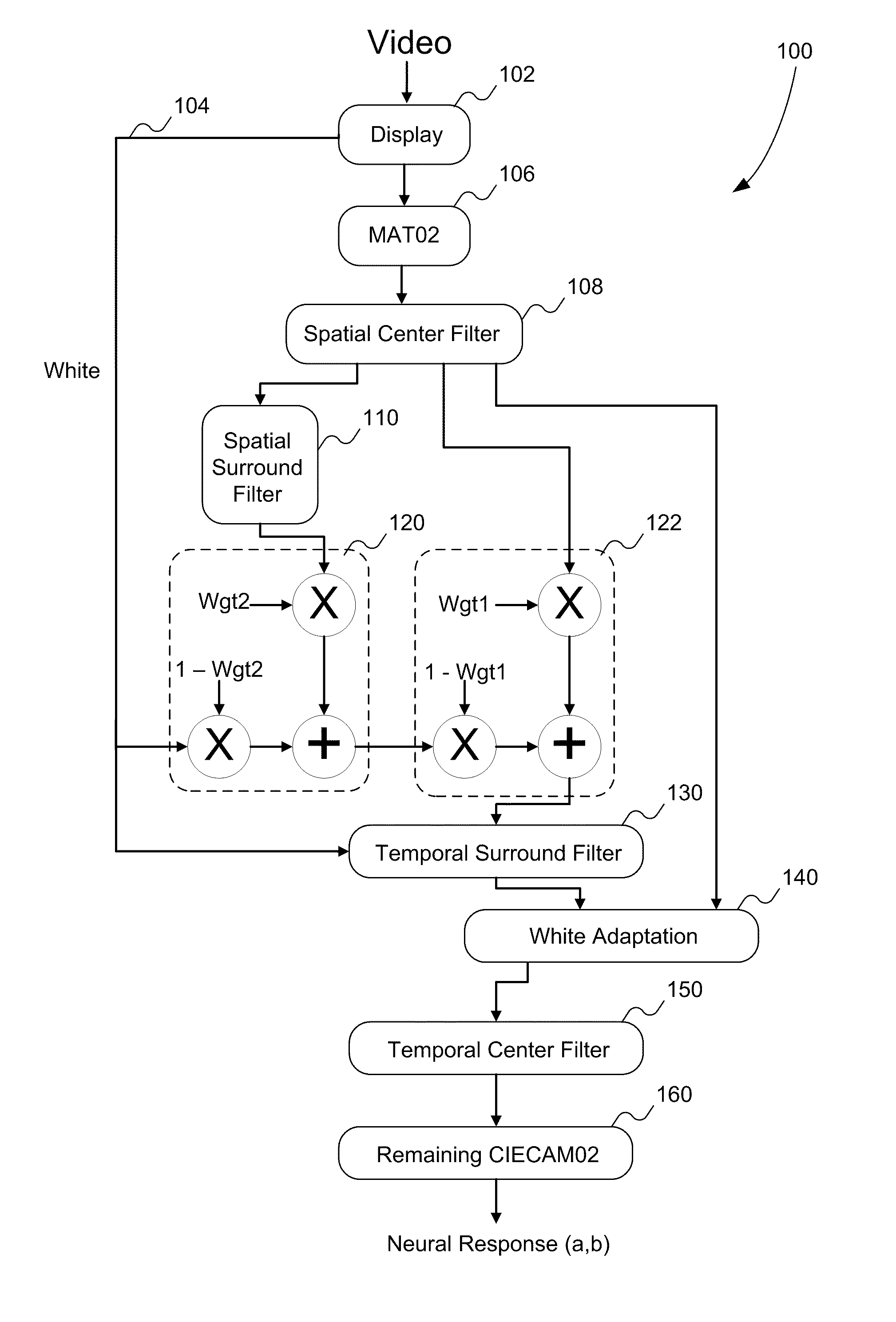
  • Method and apparatus for implementing moving image color appearance model for video quality ratings prediction
  • Method and apparatus for implementing moving image color appearance model for video quality ratings prediction
  • Method and apparatus for implementing moving image color appearance model for video quality ratings prediction

Examples


example filter

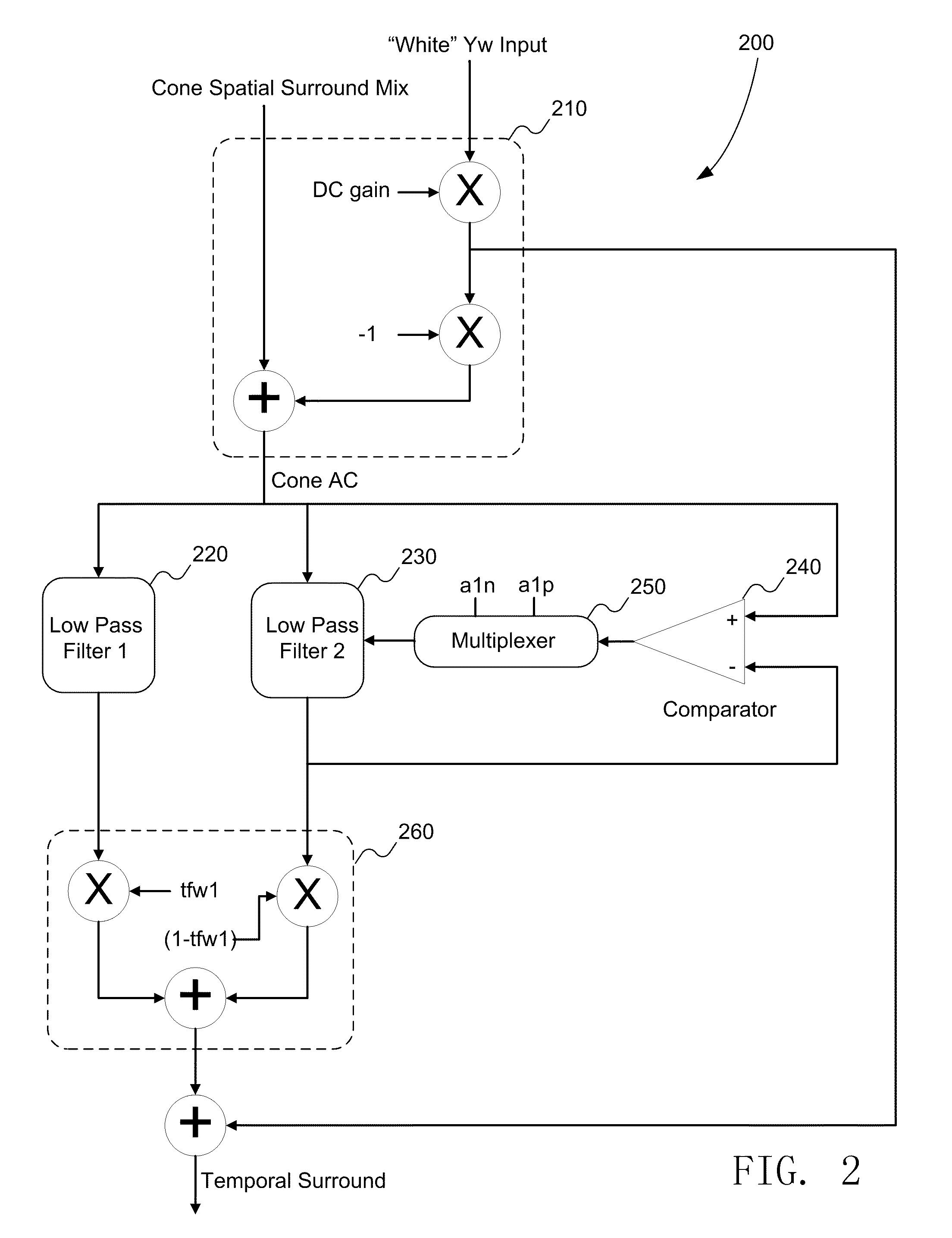
[0043 details for LPF 220 and LPF 230 are given in Table 2.

TABLE 2    LPF1: Adaptive Lum Filter of U.S. Pat. No. 6,907,143,referred to as temporal surround:    with adaptation parameters = 0 and       a1 = 0.999516, b0 = 1 − a1      for sample rate of 60Samples / second.    LPF2: Adaptive Lum Filter of U.S. Pat. No. 6,907,143,referred to as temporal surround:    with adaptation parameters = 0 and       a1 = a1n if LPF2 output > LPF2 input, else a1 = a1p:       a1n = 0.99370       a1p = 0.9854      for sample rate of 60Samples / second.

[0044]The Dirac delta impulse response of LPF 220 for particular inputs is shown in FIG. 3. The two curves 310 and 320 represent 10 and 60 samples per second, respectively. This illustrates an example of maintaining filter response at two different frame rates, the temporal sample rate adaptation requirement met by using the adaptive integrator of the above-incorporated Ferguson reference.

[0045]The overall response for the temporal surround filter 200 is n...


PUM


Abstract

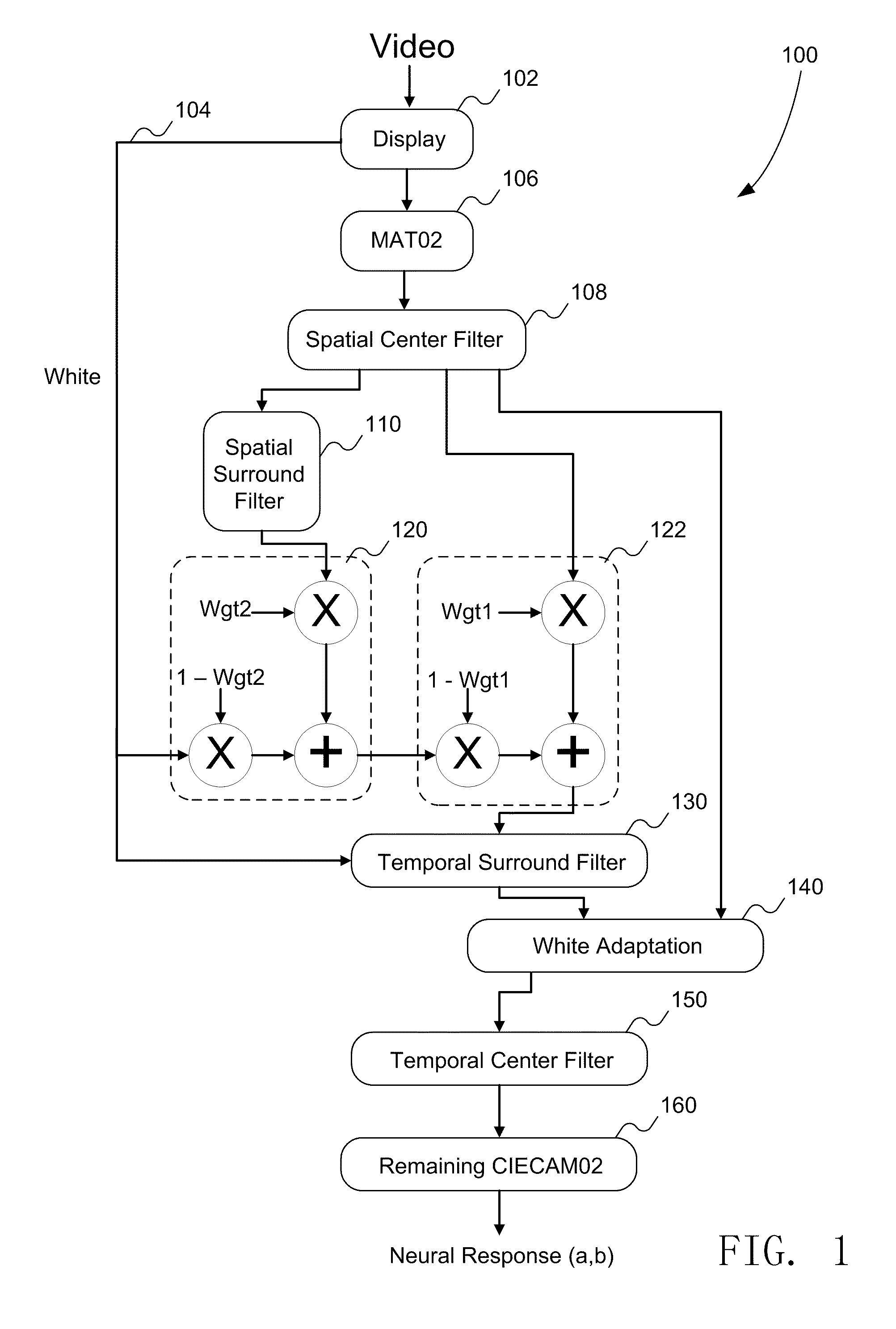
Embodiments of the invention include systems and methods for predicting video quality through human vision perceptual color response and associated perceptual differences of video relative to a reference. Embodiments include a model of the human vision system developed as an extension to CIECAM02 to predict the macro-behavioral response to light stimuli with the following varying parameters, in addition to the parameters relevant to CIECAM02: spatial frequency, temporal frequency, angular extent, temporal extent, and surround.

Description

CROSS REFERENCE TO RELATED APPLICATIONS[0001]This application claims the benefit of U.S. Provisional Application No. 61 / 122,221 filed Dec. 12, 2008, which is incorporated herein by reference.[0002]This application is related to U.S. application Ser. No. ______ (attorney docket 8474), filed Dec. 10, 2009, entitled METHOD AND APPARATUS FOR AUTOMATIC ILLUMINANT COMPENSATION IN VIDEO SURVEILLANCE, which claims the benefit of U.S. Provisional Application No. 61 / 122,221 filed Dec. 12, 2008, which is incorporated herein by reference.FIELD OF THE INVENTION[0003]This disclosure is related to video test and measurement equipment, and more particularly to picture quality measurements for video.BACKGROUND[0004]When video or image stream is manipulated, for example when a video is compressed so that it may be stored on a DVD or transmitted over a television channel, or when video is transcoded from one format to another, the manipulations introduce artifacts from the compression or conversion in...

Claims


Application Information

Patent Timeline
Patent Type & Authority Applications(United States)
IPC IPC(8): H04N17/00
CPCH04N9/73
Inventor FERGUSON, KEVIN M.
Owner PROJECT GIANTS LLC
Learn More