
System and method for applying correction factors related to ambient conditions

a technology of ambient conditions and factors, applied in the field of colorimeters, can solve the problems of incompatibility, inability to solve or otherwise address incompatibility, and variation in mounting distance of early devices developed under the standards, and achieve excellent correlation

Active Publication Date: 2009-03-03
X RITE SWITZERLAND
View PDF22 Cites 4 Cited by
  • Summary
  • Abstract
  • Description
  • Claims
  • Application Information

AI Technical Summary

Benefits of technology

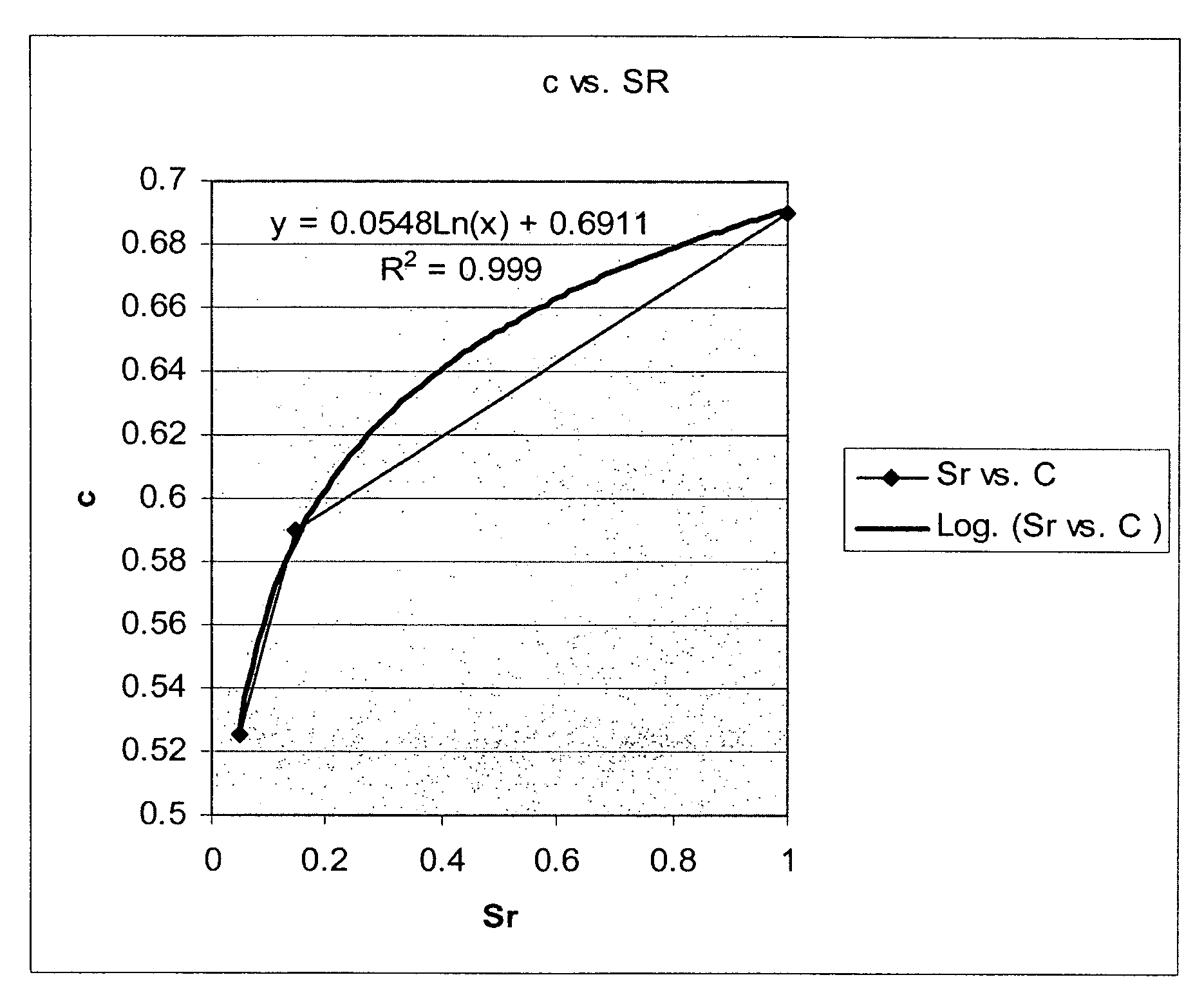
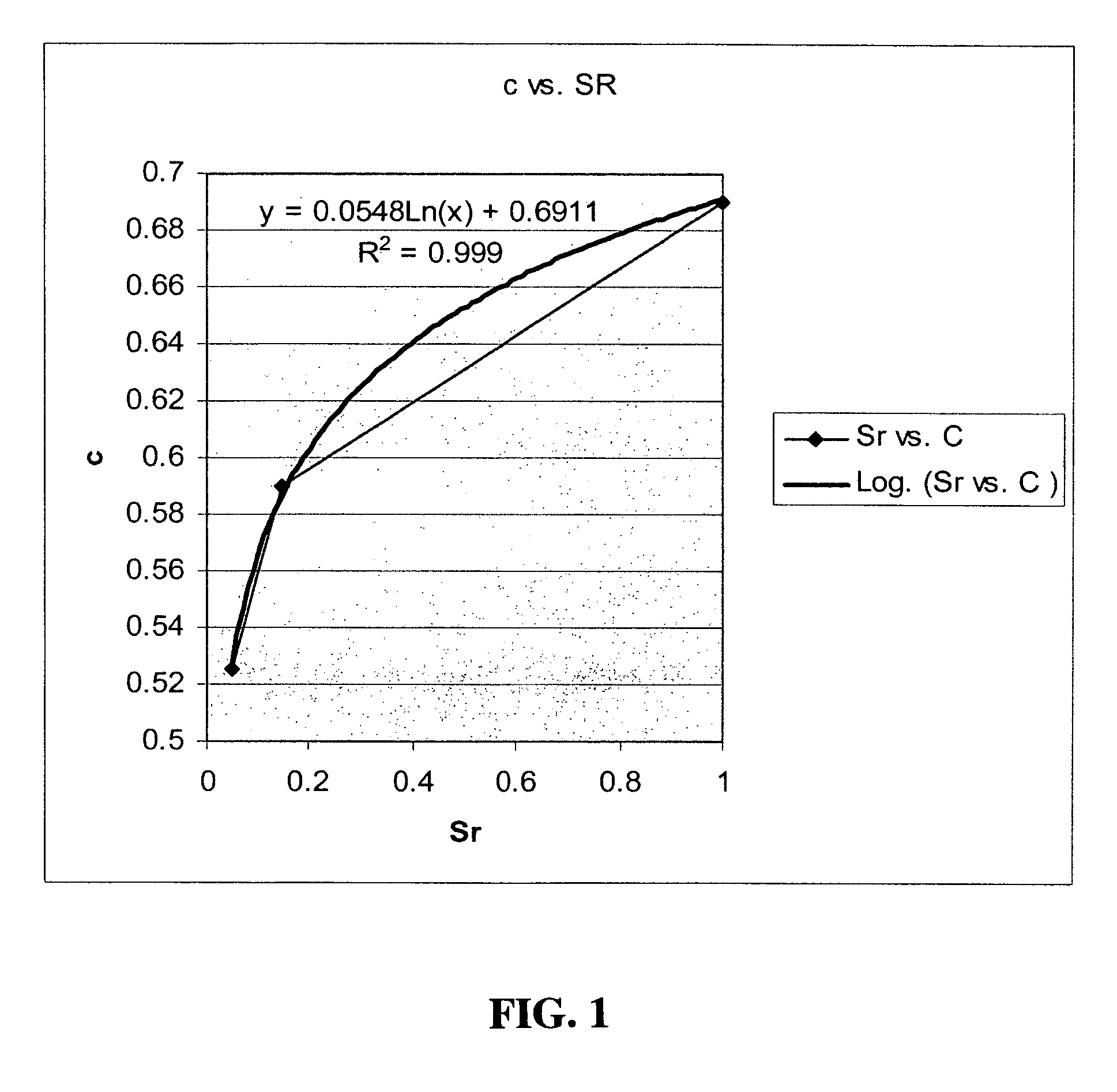
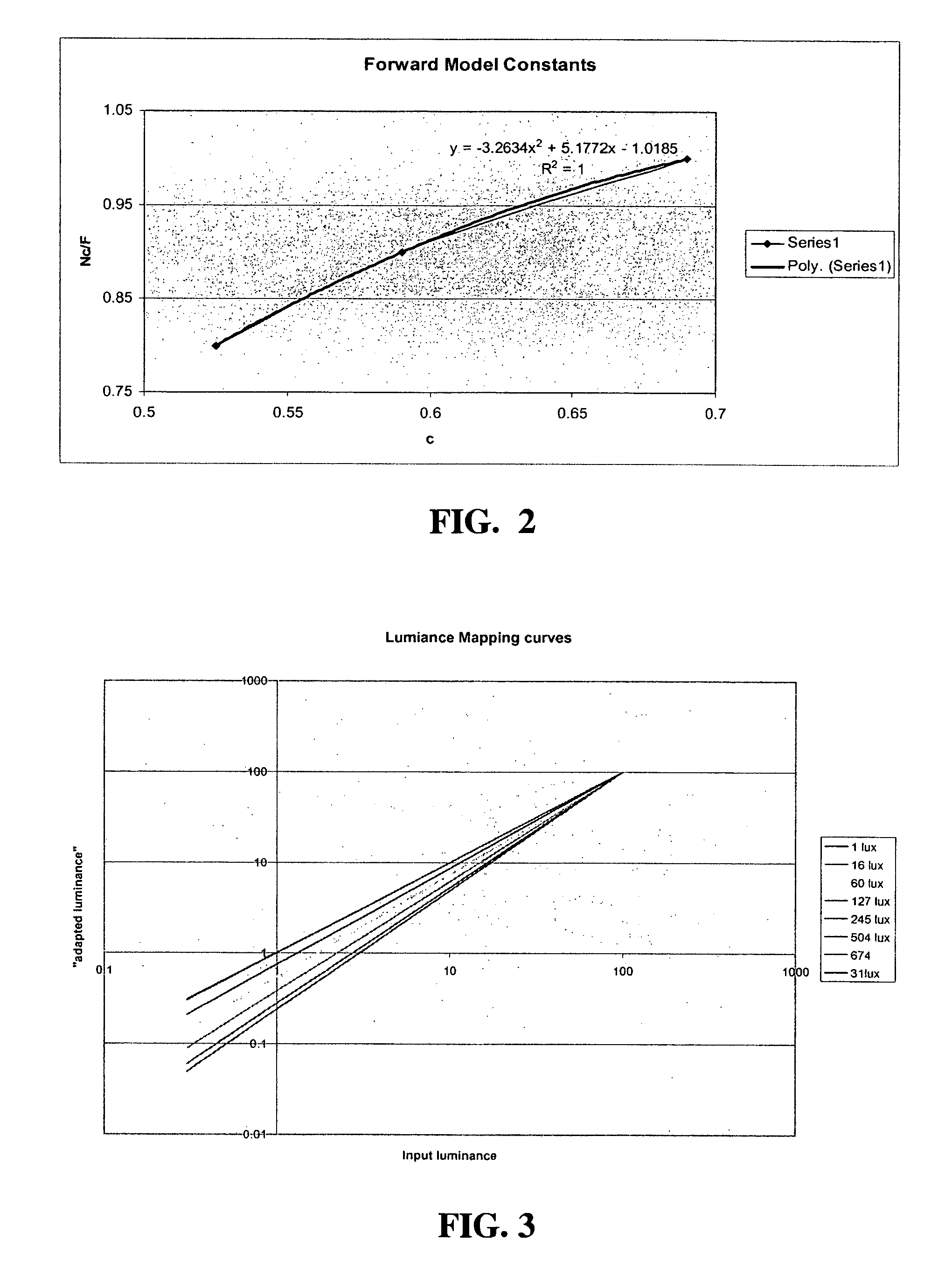
[0024]The present disclosure provides advantageous systems and methods for applying correction factors related to display systems and, more particularly, to a colorimeter that is programmed through software and / or hardware to calculate and apply one or more correction factors to compensate for ambient conditions. The disclosed correction system and methodology streamlines the calculations associated with the C.I.E. Color Appearance Model specification, i.e., the CIECAM02 specification, such that ambient condition corrections may be implemented on an expeditious, real-time basis, without the need for substantial processing infrastructure. Despite the streamlined nature of the disclosed correction system and methodology, the systems and methods of the present disclosure achieve excellent correlation relative to the CIECAM02 specification across a broad range of ambient conditions.
[0026]Thus, according to exemplary embodiments of the present disclosure, an appropriate color appearance model is achieved through a polynomial-based correction algorithm that generates gamma correction coefficients to correct a display appearance based on illuminance levels, i.e., over a range of illumination levels. The disclosed polynomial-based correction algorithm has demonstrated excellent correlation with data collected from CIECAM02 modeling of data for a range of illumination conditions, e.g., dark, dim and light conditions. Implementation of the disclosed polynomial-based algorithm is generally achieved through appropriate software programming, e.g., firmware, associated with a colorimeter or other color measurement system or a hardware-based implementation. The polynomial-based algorithm is generally run on a processing unit associated with the colorimeter, although alternative implementations may be employed, e.g., network-based processing. The gamma correction factors generated by the disclosed polynomial-based algorithm are applied to a display, e.g., an LCD, to provide enhanced viewing of the display based on existing ambient conditions.

Problems solved by technology

Such incompatibilities have yet to be resolved or otherwise addressed.
In addition, early devices developed under the standards were relatively costly.
However, such a design does not correspond to the field of view of the human eye.
Such designs generally cause variations in the mounting distance due to leaking-based relaxation of the suction cups.
This variation, in conjunction with a fixed-distance between the aperture plate and the sensor, causes the field of view to vary as well, and adversely impacts the accuracy of the associated measurements.
However, this sensor reference does not assure accurate alignment of the sensor in the plane parallel to the measured surface, and there is no means for locating the center of the senor lens to the center of the optical path.
Such limitations contribute to undesirable decay of the SNR, as well as to inadequate color measurement accuracy.
While prior art colorimeters concentrated on measurement of what the sensor “sees”, effects on perception resulting from ambient light impinging upon the source has eluded the existing colorimeter art.
If this in turn leads to arbitrary adjustment of the brightness control (when available such as with analog displays), system calibration can be severely hampered.
Brightness controls on displays are notoriously non-linear.
Uncalled for adjustment of brightness by the user can introduce severe degradation of contrast, linearity and perceived anomalies.
Further image contrast and the ability to discern detail at different levels of image luminosity can be adversely affected by ambient illuminance of the area immediately adjacent to the image.
While it has been recognized that ambient light presents many problems and challenges to colorimeter measurement quality, to date the most sophisticated approaches are limited to taking a reading of the ambient at a point, and then depending on that measurement of ambient light for all ensuing ambient light compensation.
Nonlinearities of displays, complexity of color measurement, response of the human eye, effects of viewing room ambient conditions, measurement degradation due to extraneous other factors, and the interactions between these factors make measurement and compensation challenging at the least.

Method used


Image

  • System and method for applying correction factors related to ambient conditions
  • System and method for applying correction factors related to ambient conditions
  • System and method for applying correction factors related to ambient conditions

Examples


Embodiment Construction

)

[0051]Embodiments of the present disclosure provide colorimeters capable of measurement of emitted light from sources that are static, such as LCD displays, illuminated printed or graphic matter, and / or temporally active sources, such as CRT displays or strobed printed and graphic matter. The assembly and configuration of exemplary embodiments of the disclosed devices operate to maximize the signal-to-noise ratio (SNR), as well as to provide an optimal field of view that simulates the field of view of the human eye. Geometric elements and features of the device design, in conjunction with the assembly procedure assure precise alignment of optical elements, including sensors, filters, and other elements within the enclosure and optical path.

[0052]The present disclosure further provides advantageous systems and methods for applying correction factors related to display systems, such correction factors advantageously taking into consideration ambient light conditions. According to exe...


PUM


Abstract

A method and system for effecting an appearance model correction for a display unit, e.g., a CRT, using a polynomial-based algorithm is described. The correction may be effected in real time and is based on gamma values associated with the display. Strong correlations with the CIECAM02 specification are achieved according to the present disclosure. The correction functionality may be implemented using a colorimeter that includes a plurality of sensors / filter systems with non overlappng spectral responses, adequate for providing data capable of translation into standard coordinates system such as, CIE XYZ, CIE L*a*b*, or CIE Luv, as well as non-standard operable coordinate systems. The field of view of the colorimeter is chosen to closely track the response of the human eye using an optical path configured to select and limit the field of view in a manner that is insensitive to placement of the colorimeter on the source image. The optical path from the source image to the sensor is configured to select preferred light rays while rejecting undesirable light rays to maximize the signal / noise ratio. A rearward facing sensor channel is included to simultaneously measure ambient light impinging on the source image and feedback means to provide status and / or change of information.

Description

CROSS-REFERENCE TO RELATED APPLICATION(S)[0001]The present application claims the benefit of a co-pending, commonly assigned provisional patent application entitled “Improved Colorimetry by Proper Handling of Ambient Light,” which was filed on Feb. 15, 2005 and assigned Ser. No. 60 / 653,048. In addition, the present application claims the benefit of a co-pending, commonly assigned non-provisional patent application entitled “Method and Apparatus for Improved Colorimetry,” which was filed on Sep. 30, 2005 and assigned Ser. No. 11 / 240,917. The entire contents of the foregoing provisional patent application and non-provisional patent application are hereby incorporated herein by reference.BACKGROUND[0002]1. Technical Field[0003]The present disclosure relates to systems and methods for applying correction factors related to display systems and, more particularly, to a colorimeter that is programmed through software and / or hardware to calculate and apply one or more correction factors to ...

Claims


Application Information

Patent Timeline
Patent Type & Authority Patents(United States)
IPC IPC(8): G01J3/46
CPCG01J3/02G01J3/0256G01J3/0262G01J3/0272G01J3/0289G01J3/0291G01J3/46G01J3/51G01J3/524G01J3/462G01J3/465G01J3/513G09G2320/0693
Inventor LIANZA, THOMAS A.FEDERICO, RICHARD A.LUTZ, CARL D.
Owner X RITE SWITZERLAND
Learn More