Cardiac monitoring device and a rate responsive pacemaker system

a monitoring device and pacemaker technology, applied in the field of cardiac monitoring devices, can solve the problems of unregistered devices, unacceptable size and weight of operations, and requiring quite a lot of energy for their operation

Inactive Publication Date: 2002-07-16
PACESETTER AB
View PDF6 Cites 53 Cited by
  • Summary
  • Abstract
  • Description
  • Claims
  • Application Information

AI Technical Summary

Problems solved by technology

The catheter described is primarily intended for examining a visualizing a heart, but is obviously not meant for implantation and would not possibly be used for such a purpose as it is considered highly energy consuming and would be of unacceptable size and weight for operation as an implantable equipment.
However, the device is not provided to register the delay between the transmission of the signals and the receipt of the echoes thereof in order to derive from the delay a p

Method used


Image

  • Cardiac monitoring device and a rate responsive pacemaker system
  • Cardiac monitoring device and a rate responsive pacemaker system

Examples


Embodiment Construction

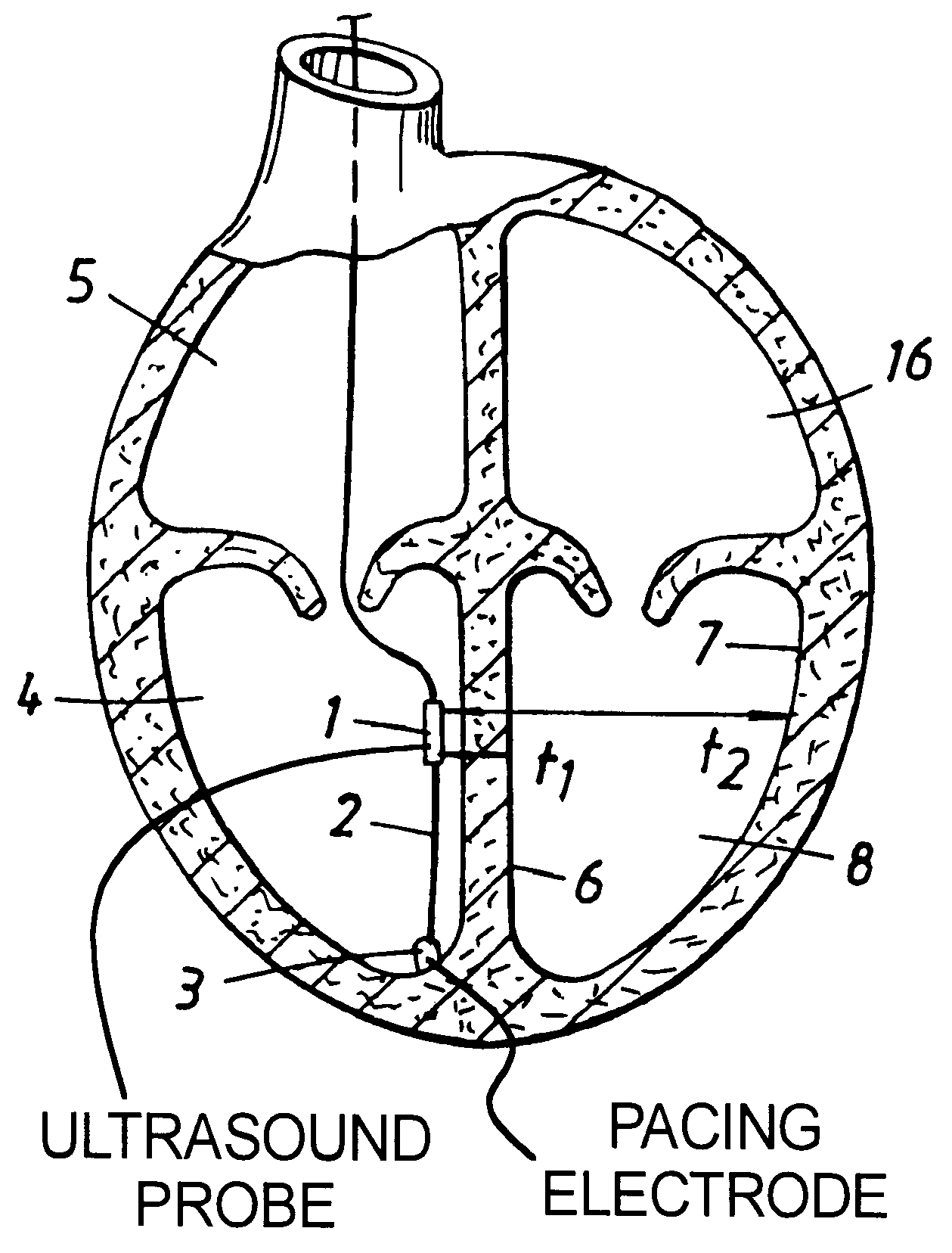
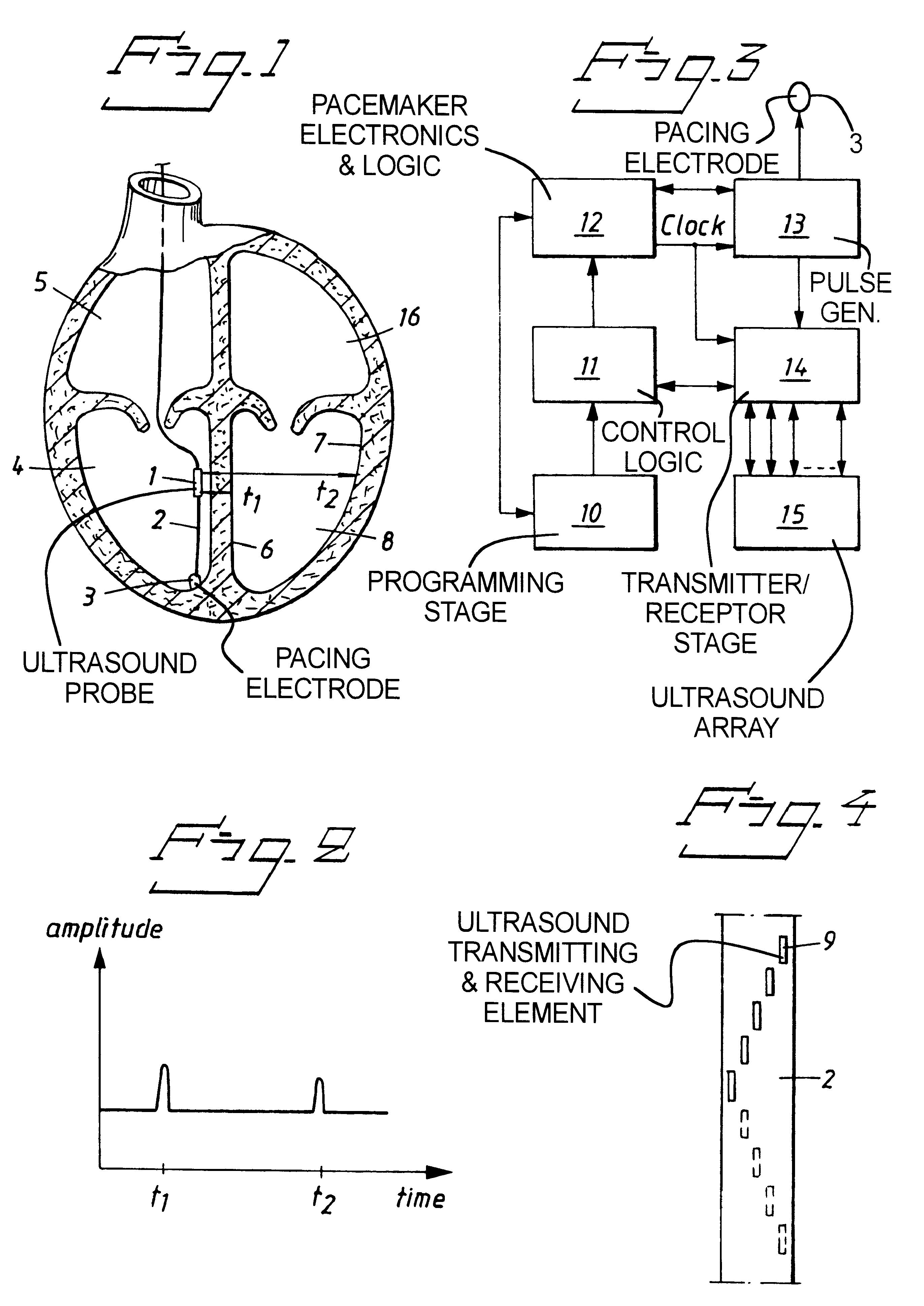
According to FIG. 1 a simple amplitude mode (A-mode) ultrasound probe 1 is mounted near the distal end of a pacemaker lead 2. A tip 3 (at which a pacing electrode may be present) of the lead 2 is anchored at or near the apex of the right ventricle 4 of a heart 5. The ultrasound probe 1 is arranged to detect the position of the medial portion 6 and lateral portion 7 of the endocardial wall of the left ventricle 8 respectively, these portions 6 and 7 defining a cardiac segment from which an echo of a signal emitted by the ultrasound probe 1 is received by the ultrasound probe 1.

The ultrasound probe 1 contains at least one element 9 for emitting a signal and receiving at least one echo of this signal reflected from at least one cardiac segment, here constituted by the medial and lateral portions 6 and 7 of the endocardium. The element 9 may be an ultrasound (piezoelectric) crystal, and the ultrasound probe 1 can contain an array of such elements 9, helically arranged around the periphe...


PUM


Abstract

An implantable cardiac monitoring device as an A-mode ultrasound probe which is adapted to be positioned in the right ventricle of a heart, and which emits an ultrasound signal which is reflected from one cardiac segment of the left ventricle of the heart, and the ultrasound probe receives the resulting echo signal. The delay between the emission of the ultrasound signal and the reception of the resulting echo is measured, and from this delay a position of the cardiac segment is determined. The position of this cardiac segment, at least one reflecting the signal, is related to cardiac performance, and thus the monitoring device determines, from the detected position of the cardiac segment, the cardiac performance.

Description

1. Field of the InventionThe present invention relates to a cardiac monitoring device of the type having a component for transmitting a signal and receiving at least one echo of the signal reflected from at least one cardiac segment, a position of which, at least when reflecting the signal is related to the cardiac performance of a heart, and circuitry to determine a delay between the transmission of the signal and the receipt of the echo, and to derive from the delay the position of the cardiac segment.The invention also relates to a rate responsive pacemaker system containing such a device.2. Description of the Prior ArtSince a device of the above type is particularly suited for an application wherein it is arranged to register the position of a cardiac wall segment, it will, by way of example only, be described in relation to such an application hereinafter. Thereby, the cardiac performance refers to cardiac output and / or other parameters related to cardiac frequency, such as bea...

Claims


Application Information

Patent Timeline
IPC IPC(8): A61B8/08A61N1/365A61B8/12
CPCA61B8/0858A61N1/36528A61B8/12
Inventor HEMMINGSSON, TRYGGVE
Owner PACESETTER AB
Why Eureka
Try Eureka