Diffuser for centrifugal compressor

a centrifugal compressor and diffuser technology, applied in the direction of machines/engines, stators, liquid fuel engines, etc., can solve the problems of high-cycle fatigue, mechanical damage,

Active Publication Date: 2010-06-17
TURBO SYST SWITZERLAND LTD
View PDF3 Cites 20 Cited by
  • Summary
  • Abstract
  • Description
  • Claims
  • Application Information

AI Technical Summary

Problems solved by technology

On account of the high speed which is required for achieving the discharge pressure, the vibrations can lead in the extreme case to mechanical damage (high-cycle fatigue—HCF) in the compressor impeller blades.

Method used


Image

  • Diffuser for centrifugal compressor
  • Diffuser for centrifugal compressor
  • Diffuser for centrifugal compressor

Examples


Embodiment Construction

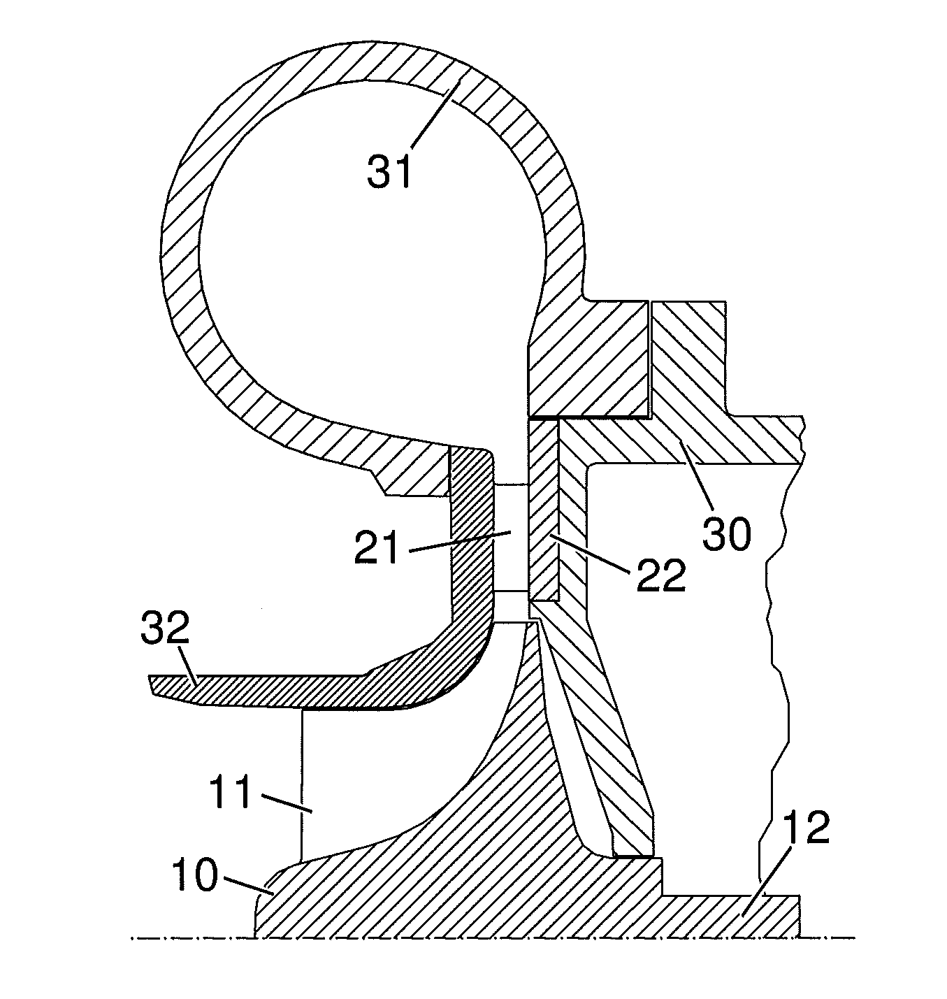
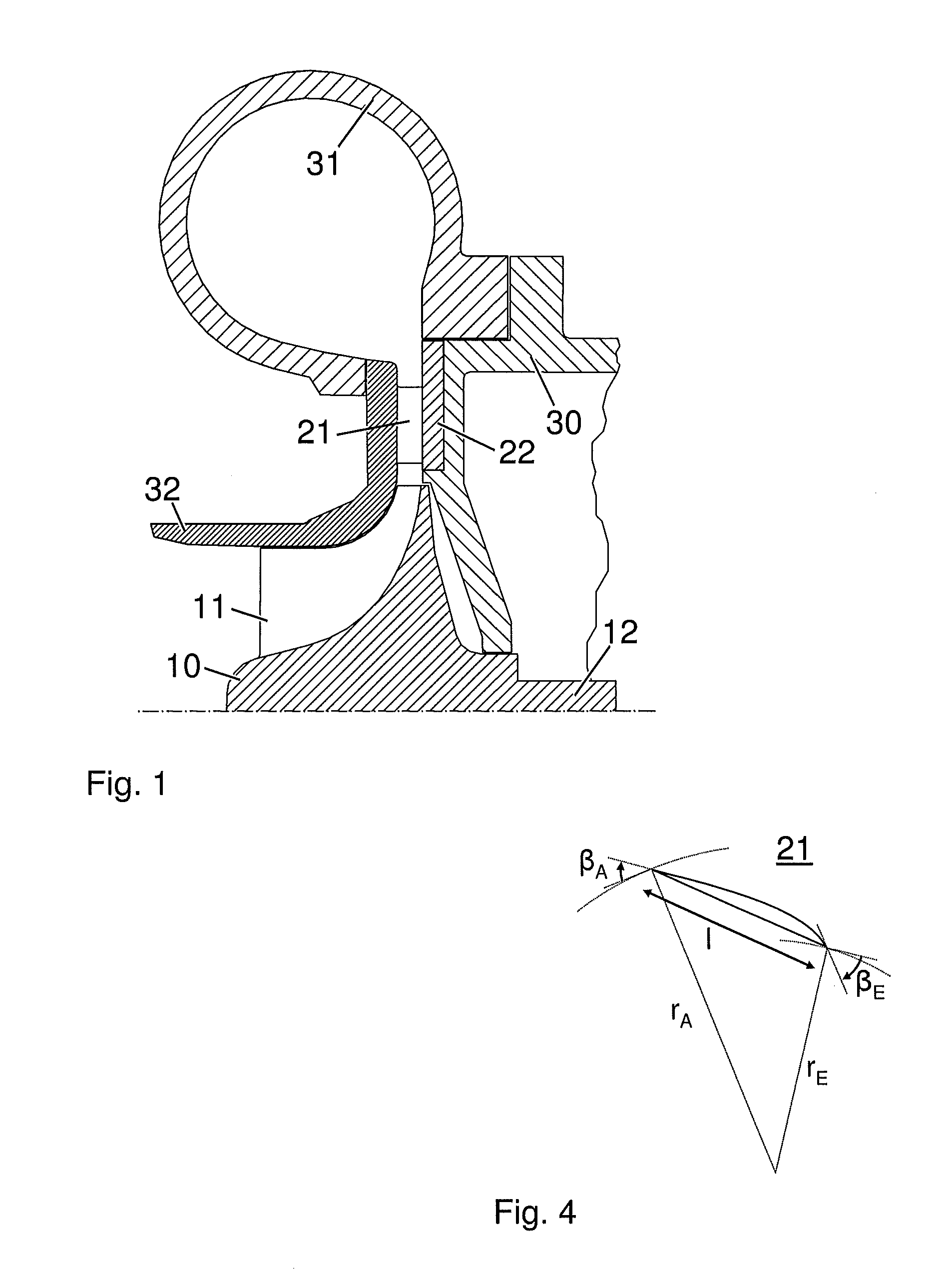
[0013]Exemplary embodiments of the present disclosure provide an improved discharge region of a centrifugal compressor in which a diffuser, in interaction with the asymmetrically formed scroll casing which is arranged downstream of the guide vanes of the diffuser, and also with the impeller blades of the centrifugal compressor impeller, causes resonance vibrations which are as low as possible.

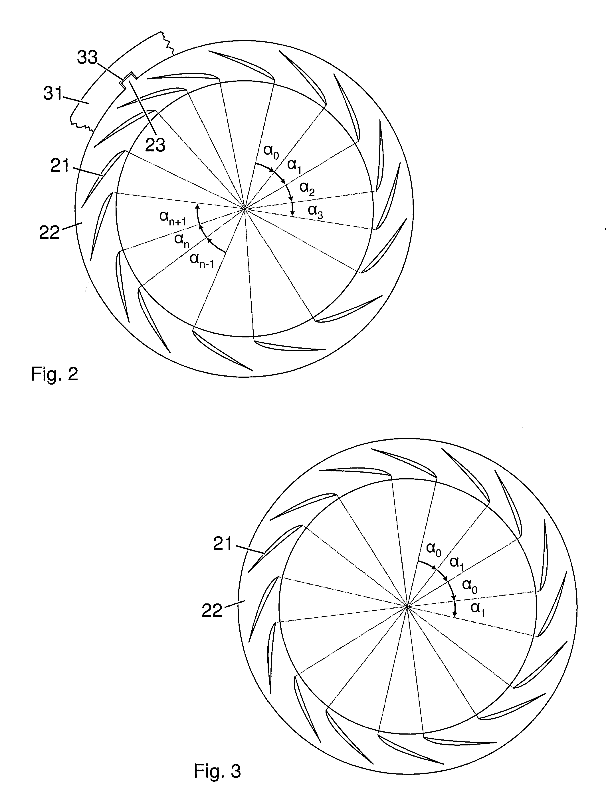
[0014]Exemplary embodiments achieve this advantageous aspect by varying the angular spacings between two adjacently arranged guide vanes of the diffuser varying. The diffuser, which is irregularly formed as a result, is arranged in a defined angular position with regard to the scroll casing which can be positioned in different angular positions in the circumferential direction.

[0015]According to an exemplary embodiment, individual guide vane pairs can have an angular spacing which differs from the remaining guide vane pairs.

[0016]In a further exemplary embodiment, a plurality of guide vane pair...


PUM


Abstract

A discharge region of a centrifugal compressor is provided. A scroll casing is asymmetrically formed in a circumferential direction and configured to be positioned in different angular positions in the circumferential direction. A vaned diffuser is configured to be positioned in different angular positions in the circumferential direction. The vaned diffuser includes a plurality of guide elements configured to be arranged in a distributed manner in the circumferential direction. Means are provided for positioning the vaned diffuser with regard to an angular position of the asymmetrically formed scroll casing. An angular spacing of two guide elements which are arranged adjacently to each other differs from an angular spacing of two other guide elements which are arranged adjacently to each other. By varying the angular spacings between two adjacent guide vanes of a diffuser along the circumference, the resonance vibration of the compressor can be reduced.

Description

RELATED APPLICATIONS[0001]This application claims priority as a continuation application under 35 U.S.C. §120 to PCT / EP2008 / 058941, which was filed as an International Application on Jul. 9, 2008 designating the U.S., and which claims priority to European Application 07112348.3 filed in Europe on Jul. 12, 2007. The entire contents of these applications are hereby incorporated by reference in their entireties.FIELD[0002]The present disclosure relates to the field of exhaust turbochargers, including exhaust turbochargers for charged internal combustion engines, for example. More particularly, the present disclosure relates to a discharge region of a centrifugal compressor of such exhaust gas turbochargers, wherein the discharge region is arranged downstream of a compressor impeller and includes a vaned diffuser and an asymmetrically formed scroll casing.BACKGROUND INFORMATION[0003]In modern turbochargers, single-stage centrifugal compressors with vaned diffusers are used to increase t...

Claims


Application Information

Patent Timeline
Patent Type & Authority Applications(United States)
IPC IPC(8): F04D29/44
CPCF01D9/02F04D29/444F04D29/666F05D2220/40F05D2260/96F04D29/667F05D2250/52F05D2260/961F02C6/12F04D29/54F04D29/66
Inventor RODUNER, CHRISTIANPHILLIPSEN, BENTROBINSON, DOUGLAS
Owner TURBO SYST SWITZERLAND LTD
Why Eureka
Try Eureka