
Quick connect-disconnect protection ring for printing sleeves

a protection ring and printing sleeve technology, which is applied in printing presses, rotary presses, printing, etc., can solve the problems of compromising the ability to ensure the requisite repeatable alignment of the sleeve and the mandrel, affecting the use of the sleeve for further printing jobs, and reducing the service life of the sleeve, so as to achieve simple and reliably protect the sleeve from collisions

Inactive Publication Date: 2010-06-24
ROSSINI SPA
View PDF10 Cites 1 Cited by
  • Summary
  • Abstract
  • Description
  • Claims
  • Application Information

AI Technical Summary

Benefits of technology

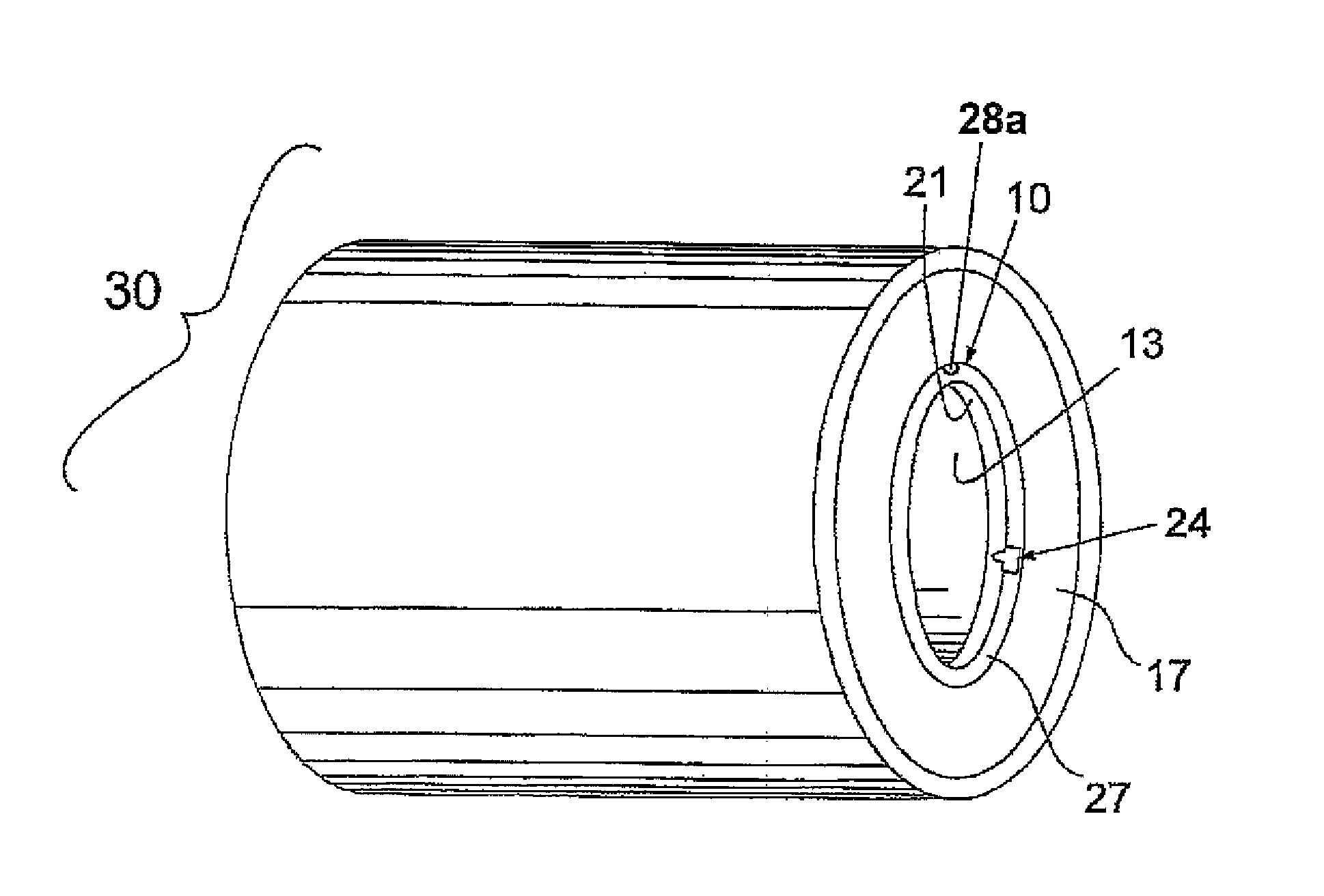
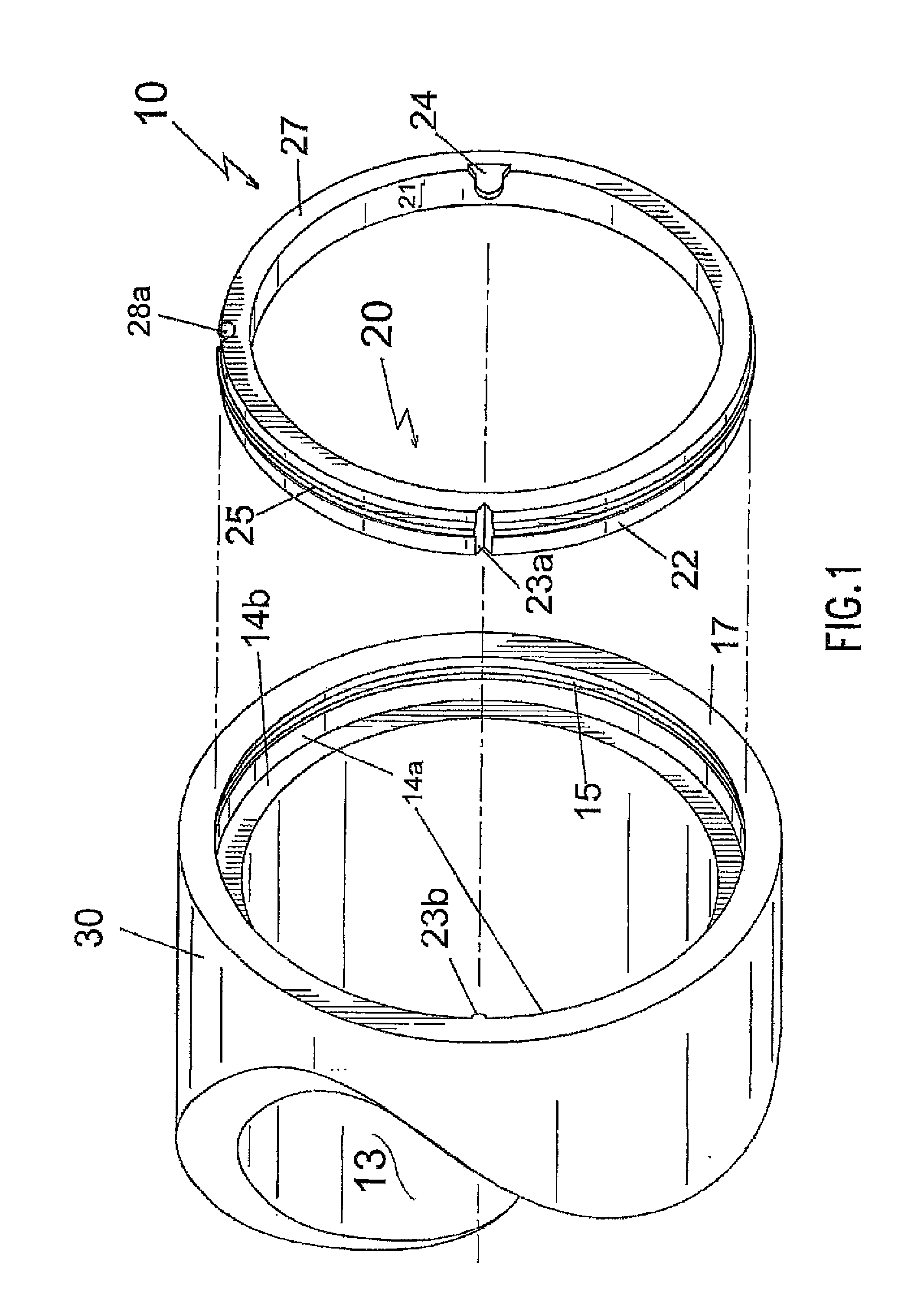
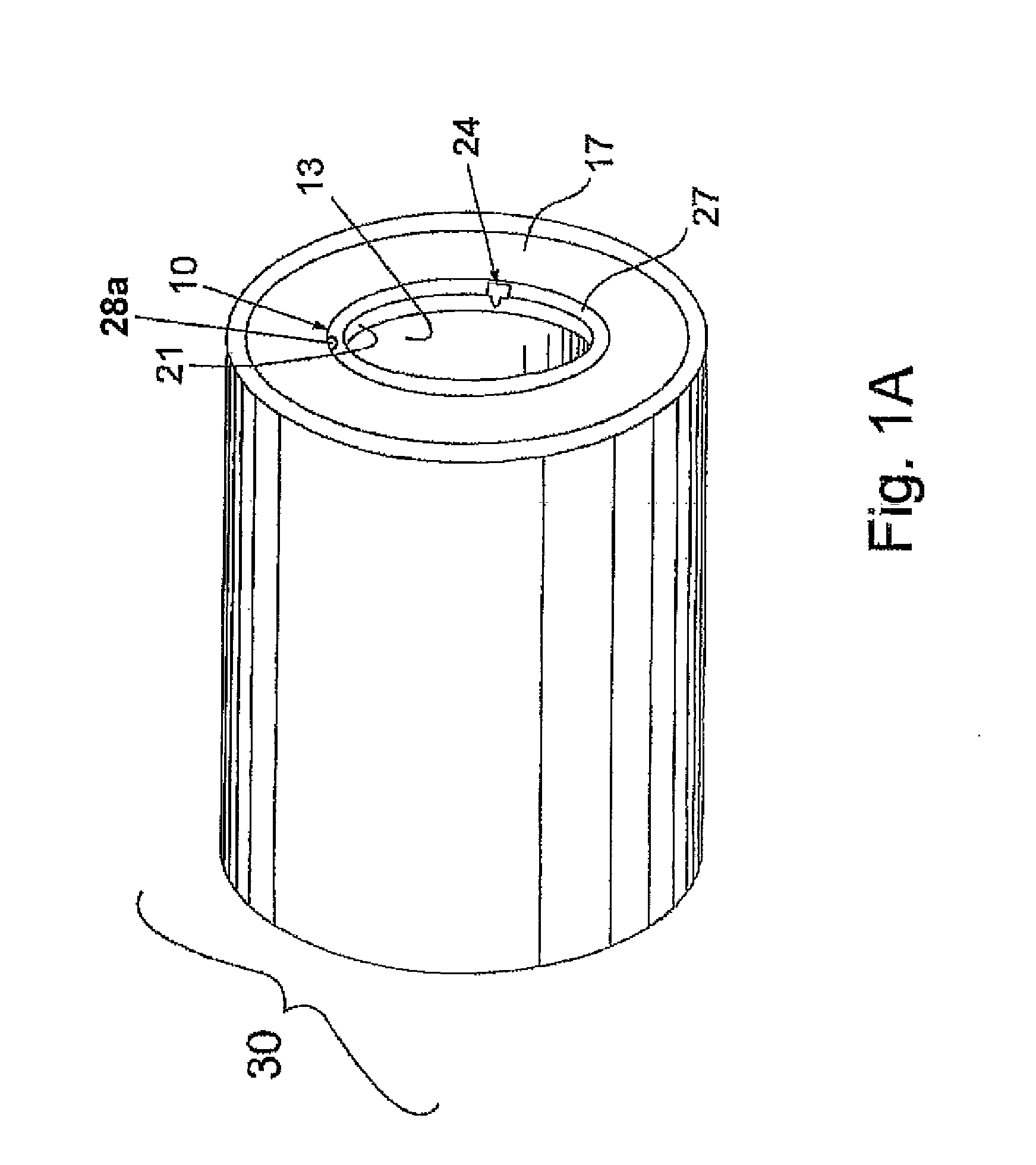
[0009]A principal object of the present invention is to provide a way to ensure that the sleeve's free edge containing the locating notch can be simply and reliably protected from collisions against the register pin of the mandrel of a printing machine.
[0010]Another principal object of the present invention is to provide a way to ensure that the register pin of the mandrel of a printing machine can be simply and reliably protected from collisions against the sleeve's free edge containing the locating notch.
[0011]A further principal object of the present invention is to provide a replaceable protection ring able to be associated in a simple and reliable manner with the free edge of the sleeve containing the locating notch for the purpose of protecting it from collisions against the register pin.
[0012]An additional principal object of the present invention is to provide a replaceable protection ring able to be associated in a simple and reliable manner with the free edge of the sleeve containing the locating notch for the purpose of protecting the register pin from damage resulting from collisions against the locating notch.
[0013]A particular object of the invention is to provide a ring of the stated type which can be uniquely coupled to the sleeve to enable reliable and correct mounting of this sleeve onto the rotary mandrel or support cylinder.
[0015]Still another object is to provide a ring of the stated type that easily and inexpensively can be replaced if damaged without damaging the sleeve during the replacement process.

Problems solved by technology

As the register pins of the rotary mandrels or support cylinders are composed of metal, usually steel, whereas the sleeves are composed of composite materials, even a single such collision can damage the free edge of the sleeve containing the register recess.
Such damage is likely to occur in particular in proximity to the locating notch, hence compromising the ability to ensure the requisite repeatable alignment of the sleeve and the mandrel.
Moreover, the damage to the edge of the sleeve eventually adversely affects the Total Indicated Runout (T.I.R.) of the sleeve and renders the sleeve unusable for further printing jobs.
Sometimes such collisions result in the severing of the register pin or sever damage to same thereby rendering the mandrel useless or at least in need of repair.
Moreover, even less violent collisions between the register pin and the annular member bearing the locating notch can result in burrs being formed in the annular member, and such burrs can mar the outer surface of the mandrel and render the mandrel useless or at least in need of repair.
Additionally, the collisions between the annular member and the register pin eventually damage the edge of the annular member sufficiently so as to render the sleeve useless, either from adversely affecting the Total Indicated Runout (T.I.R.) of the sleeve and / or damaging the locating notch so that it no longer performs the desired locating function, and in each case thereby renders the sleeve unusable for further printing jobs.

Method used


Image

  • Quick connect-disconnect protection ring for printing sleeves
  • Quick connect-disconnect protection ring for printing sleeves
  • Quick connect-disconnect protection ring for printing sleeves

Examples


Embodiment Construction

[0032]Reference now will be made in detail to presently preferred exemplary embodiments of the invention, more than one example of which being illustrated in the accompanying drawings. Each example is provided by way of explanation of the invention, which is not restricted to the specifics of the examples. In fact, it will be apparent to those skilled in the art that various modifications and variations can be made in the present invention without departing from the scope or spirit of the invention. For instance, features illustrated or described as part of one embodiment, can be used on another embodiment to yield a still further embodiment. Thus, it is intended that the present invention cover such modifications and variations as come within the scope of the appended claims and their equivalents. The same numerals are assigned to the same components throughout the drawings and description.

[0033]As shown in FIG. 1, an exemplary protection ring according to the invention is indicate...


PUM


Abstract

A protection ring for a printing sleeve such as a sleeve or cylinder carrying the characters to be printed, or an adapter sleeve for supporting said sleeve or cylinder, the sleeve to be mounted on a rotary mandrel provided with a register pin, can include an annular body to be disposed on an end edge of the sleeve. The body defines a first coupling member for its detachable coupling to the sleeve, which is provided with a second coupling member for cooperating with the first coupling member. The body includes a register notch for cooperating with the mandrel's register pin. The body includes a first orientation element for properly orienting the ring on the sleeve, to enable the ring to be disposed on the sleeve such that the register notch lies in a position suitable for cooperation with the register pin.

Description

CROSS-REFERENCE TO RELATED APPLICATIONS[0001]The present application hereby claims priority to currently pending Italian Application Serial Number MI2008A002300, filed Dec. 23, 2008.STATEMENT REGARDING FEDERALLY SPONSORED RESEARCH OR DEVELOPMENT[0002]N / ABACKGROUND OF THE INVENTION[0003]The present invention relates to a protection ring for a printing sleeve that is configured to be mounted on a rotary mandrel that is provided with a register pin.[0004]In flexographic printing, the sleeves (as used herein, this term “sleeve” meaning either “adapter” sleeves for mounting printing sleeves or printing sleeves carrying the data to be printed) are known to be mounted on a rotary support cylinder or mandrel of a printing machine. Mounting the sleeve on the mandrel can be achieved by known methods. For example, compressed air can be supplied onto the surface of mandrel to create an air cushion along which the sleeve slides onto the mandrel.[0005]To enable the sleeve to be correctly mounted ...

Claims


Application Information

Patent Timeline
IPC IPC(8): B41F27/06
CPCB41F13/10
Inventor ROSSINI, FELICE
Owner ROSSINI SPA
Learn More