
Battery charging system for mobile and accessory device

a mobile and accessory device technology, applied in the direction of battery emergency arrangements, electric vehicles, battery emergency arrangements, etc., can solve the problems of user inconvenience, constant need to recharge or replace the batteries of wireless devices, and the power requirements of wireless devices have not decreased, so as to achieve the effect of low charge and minimal downtim

Active Publication Date: 2010-06-24
APPLE INC
View PDF26 Cites 20 Cited by
  • Summary
  • Abstract
  • Description
  • Claims
  • Application Information

AI Technical Summary

Benefits of technology

[0016]According to another embodiment, a rechargeable battery may be adapted control the charging protocol for any of several goals. In one embodiment, a rechargeable battery may control the rate of charging to minimize charging time. A rechargeable battery may control the rate of charging to maximize overall battery life. A rechargeable battery may control the rate of charging to maximize the energy charged.
[0023]According to another embodiment, a host machine may be adapted control the charging protocol for any of several goals. In one embodiment, a host machine may control the rate of charging to minimize charging time. A host machine may control the rate of charging to maximize overall battery life. A host machine may control the rate of charging to maximize the energy charged.
[0028]According to an embodiment, a battery charging and monitoring system may be adapted to minimize downtime associated with recharging. In an embodiment, a system can keep a plurality of batteries that is always charged and ready for use. When a battery in a wireless device becomes drained, a user may be alerted of the location of the drained battery as well as the location of a charged battery held by the system that is ready to be swapped with the drained battery.
[0029]In an embodiment, a battery charging and monitoring system may be configured to estimate the time until each battery coupled to each of the wireless devices will need to be recharged. According to another embodiment, a battery charging and monitoring system may also be adapted to identify batteries of low charge and / or unfit quality. A battery charging and monitoring system may be adapted to assess the charge state and / or quality state of each of batteries coupled to the wireless devices by communicating wirelessly with the wireless devices. A battery charging and monitoring system may also be able to assess the charge state and / or quality state of the batteries that is being held. When a battery of unfit quality is found, the system may help users obtain a new compatible battery through an e-commerce system.

Problems solved by technology

However, even as devices have miniaturized and gone wireless, the power requirements of wireless devices have not decreased.
One problem often encountered by a user of a wireless personal area network is the constant need to re-charge or replace the batteries of the wireless devices.
Even if the devices are equipped with rechargeable batteries, a user of such a network still needs to be bothered by the tasks of plugging in each device to a power supply or replacing batteries for each device whenever power in the batteries run out.
Not only is this inconvenient, but it can also decrease productivity.
For example, when wireless device are being charged, the devices may have to be either attached by a cable to a power outlet or may have to be taken out of commission if the batteries are taken out for re-charging.
When a critical device such as a wireless mouse or wireless keyboard runs out of power, a user may have to wait until the device is charged being able to use the computer wirelessly again.
Other inconveniences exist.
The inconveniences increases the cost using wireless device and reduces workplace productivity.

Method used


Image

  • Battery charging system for mobile and accessory device
  • Battery charging system for mobile and accessory device
  • Battery charging system for mobile and accessory device

Examples


Embodiment Construction

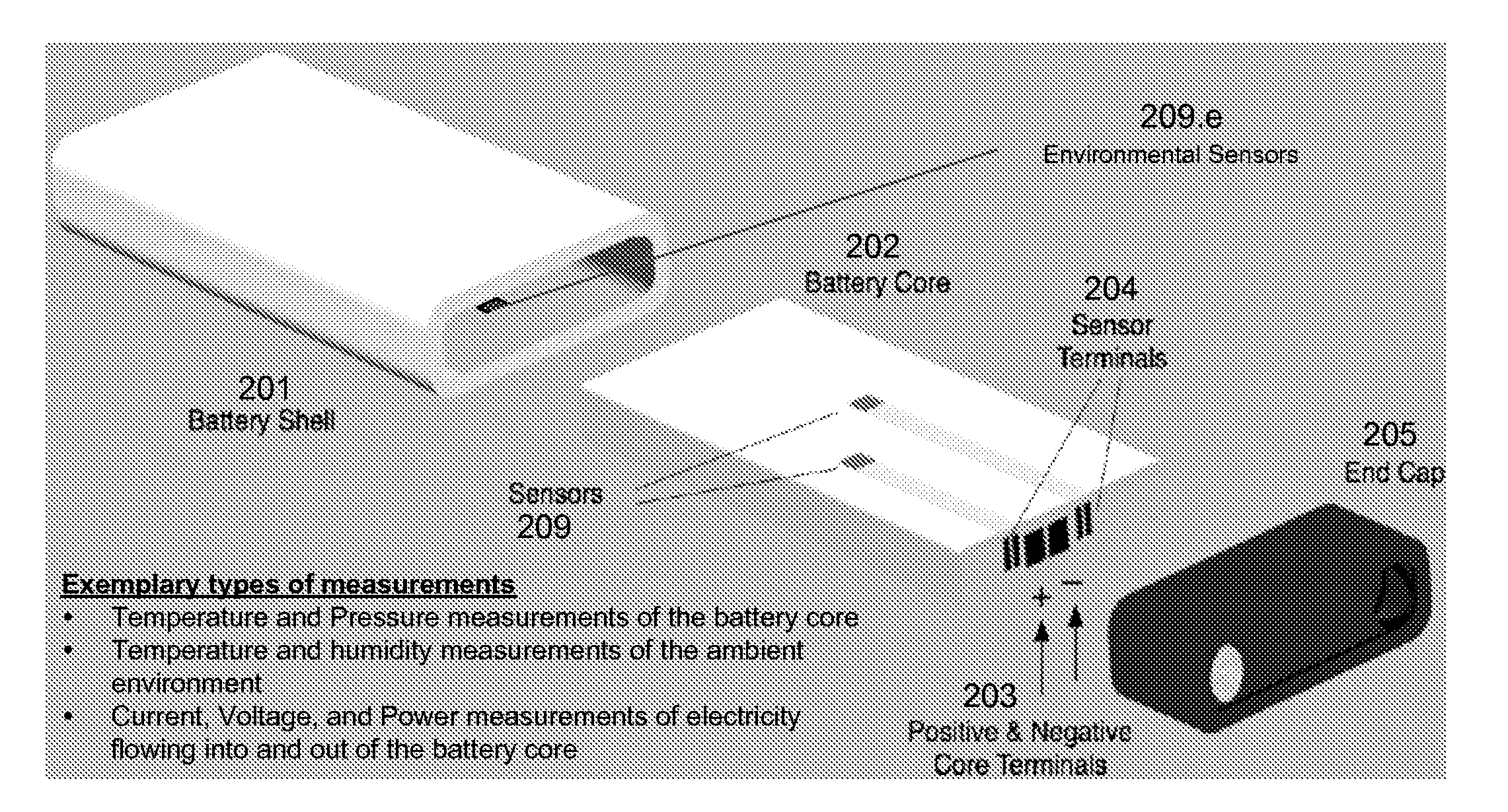
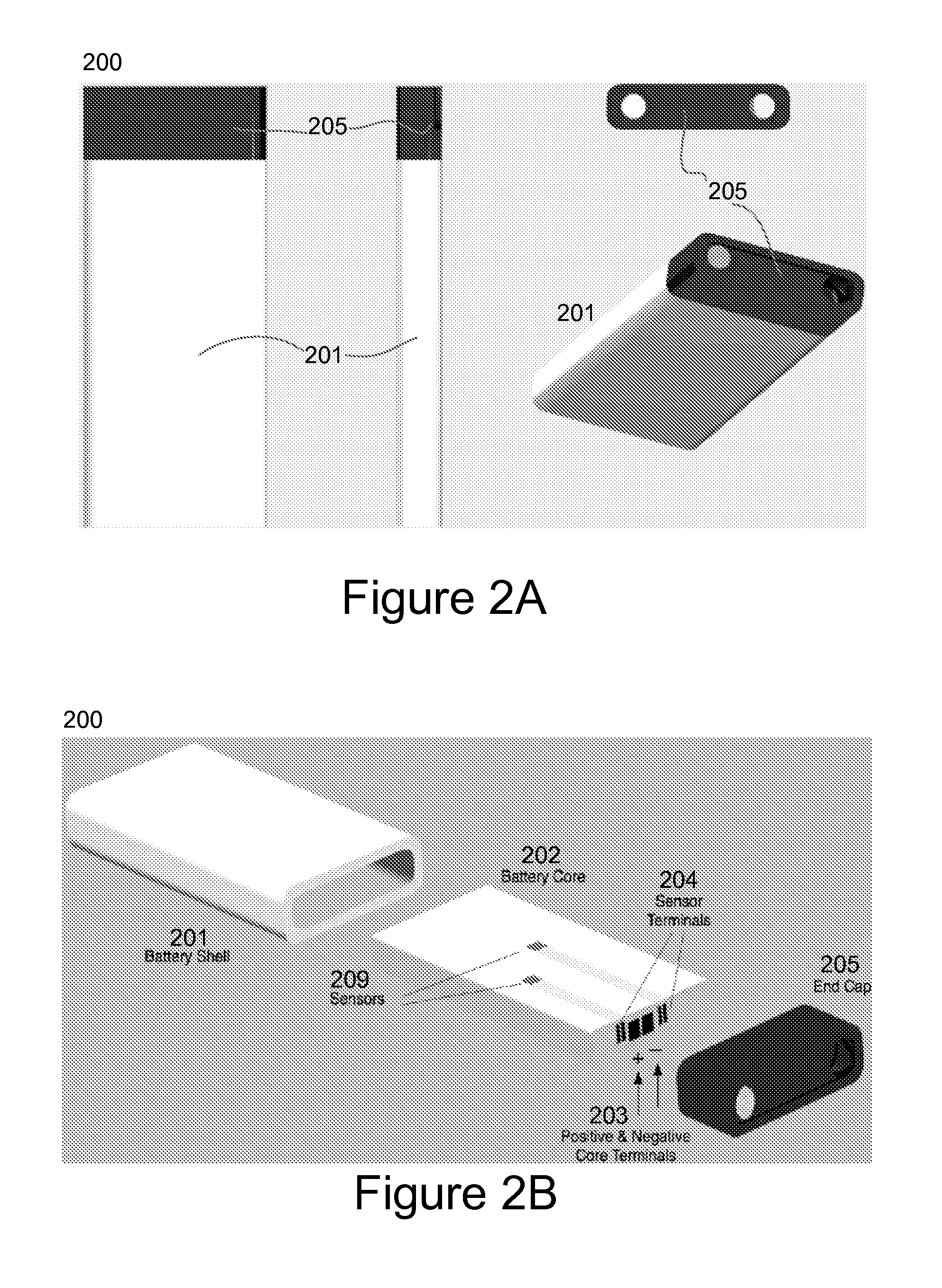
[0040]The present invention relates in general to battery charging and in particular to charging of batteries used in connection with wireless or mobile accessory devices. This section discusses the invention in terms of several exemplary embodiments to better illustrate the invention. The embodiments should not be taken by themselves to unnecessary restrict the scope of the invention.

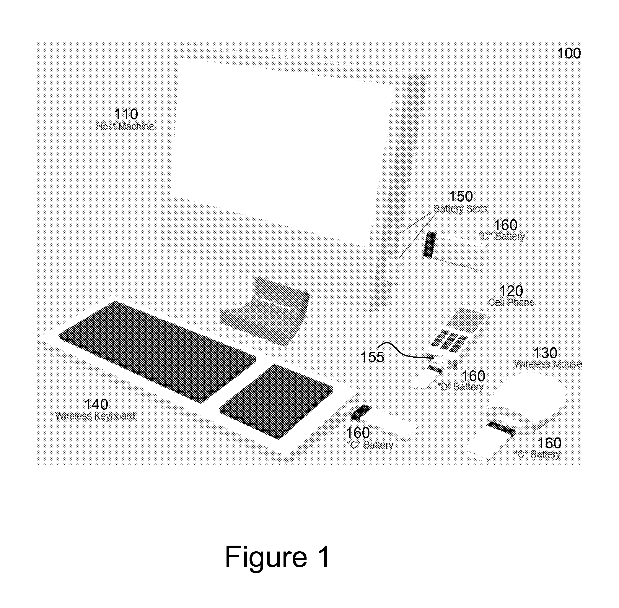
[0041]FIG. 1 illustrates a battery charging system 100 for mobile and accessory devices in accordance with a specific embodiment of the current invention. An exemplary battery charging system 100 may include host machine 110, plurality of wireless or mobile accessory devices 120, 130, 140, and plurality of rechargeable batteries 160 powering the wireless or mobile accessory devices 120, 130, 140. In an exemplary embodiment, the host machine can be a desktop personal computer, and the wireless or mobile accessory devices can be any of several wireless or mobile devices proximally located to the desktop ...


PUM

PropertyMeasurementUnit
energy storage capacityaaaaaaaaaa
transmission voltageaaaaaaaaaa

Abstract

Various embodiments of the present invention are directed at a method and system for recharging batteries for wireless electronic devices. According to one embodiment, a battery charging and monitoring system is disclosed. The system includes a host machine providing a plurality of charging slots and a plurality of wireless devices coupled to and powered by a plurality of batteries. The host machine is adapted to communicate with the plurality of wireless devices through a plurality of wireless links to monitor the plurality of batteries coupled to the wireless devices. According to another embodiment, an electronic device is disclosed. The electronic device is adapted to couple with at least a rechargeable battery and to negotiate with the rechargeable battery for an agreed range of power parameters. The electronic device is further adapted to accept power from and to provide power to the rechargeable battery at the agreed range of power parameters.

Description

CROSS-REFERENCES TO RELATED APPLICATIONS[0001]This application is a division of U.S. patent application Ser. No. 11 / 831,871, filed Jul. 31, 2007 which is incorporated by reference.BACKGROUND OF THE INVENTION[0002]As the number of small, portable, electronic devices in daily use have multiplied, so too have the need for wireless capabilities. And as computers gain increasing power, so too have the demand to integrate various types of wireless devices with personal computers. However, even as devices have miniaturized and gone wireless, the power requirements of wireless devices have not decreased. On the contrary, in some cases, the power requirements for portable wireless devices laden with new features and processing power have even increased. This trend for increased mobility and power has increased the need for longer lasting re-chargeable batteries and have propelled manufacturers of many new wireless devices to bundle their recharging units and / or batteries with their products....

Claims


Application Information

Patent Timeline
Patent Type & Authority Applications(United States)
IPC IPC(8): H02J9/00H02J7/00H01M50/247
CPCG01R31/3606G01R31/3689H02J7/0004H01M2/1022H02J7/041H01M10/482H02J7/0021Y02W30/84G01R31/371G01R31/382H02J7/00036H02J7/0071H02J7/00047Y02E60/10H02J7/04H02J7/0014H02J7/0048H01M50/247H02J50/10H02J7/0025H02J7/00045H02J7/0047H02J7/0063H01M2220/30H02J7/0045H01M10/4285H01M10/54H01M10/425H01M10/441H01M2010/4271H02J7/0013
Inventor LUDTKE, HAROLD AARON
Owner APPLE INC
Learn More