Method for displaying and operating user interface and electronic device

a user interface and electronic device technology, applied in the field of user interfaces, can solve the problems of obstructing the user from operating the user interface currently displayed on the touch screen, and generating another drawback, and achieve the effect of improving the convenience of use of the user interfa

Inactive Publication Date: 2010-07-01
COMPAL ELECTRONICS INC
View PDF12 Cites 83 Cited by
  • Summary
  • Abstract
  • Description
  • Claims
  • Application Information

AI Technical Summary

Benefits of technology

[0010]The present invention provides a method for displaying and operating a user interface which enhance usage convenience of the user interface.
[0021]From another point of view, the present invention provides an electronic device for using the aforesaid method for displaying and operating the user interface provided by the present invention. The electronic device displays the corresponding sub-menu on the area of the background frame according to the area on which the trigger signal is present, so as to enhance usage convenience of the user interface.
[0022]According to the area on which the trigger signal is present, the present invention displays the corresponding sub-menu on the same area of the background frame, thereby allowing the user to quickly summon the sub-menu. When the trigger signal moves or jumps to another area, the sub-menu presently displayed is switched to the sub-menu corresponding to the other area, so as to quickly switch among the sub-menus. In addition, when another trigger signal is received on one of the options of the sub-menu, the operating function corresponding to the option may be executed or the next level of menu corresponding to the option may be displayed. Hence, usage convenience of the user interface may be enhanced.

Problems solved by technology

However, in the standby mode, although the menu 20 may inform the user of the position to press, the menu 20 still takes up a frame displayed on the touch screen, thereby obstructing the user from operating the user interface currently displayed on the touch screen.
However, such a method generates another drawback.

Method used


Image

  • Method for displaying and operating user interface and electronic device
  • Method for displaying and operating user interface and electronic device
  • Method for displaying and operating user interface and electronic device

Examples


first embodiment

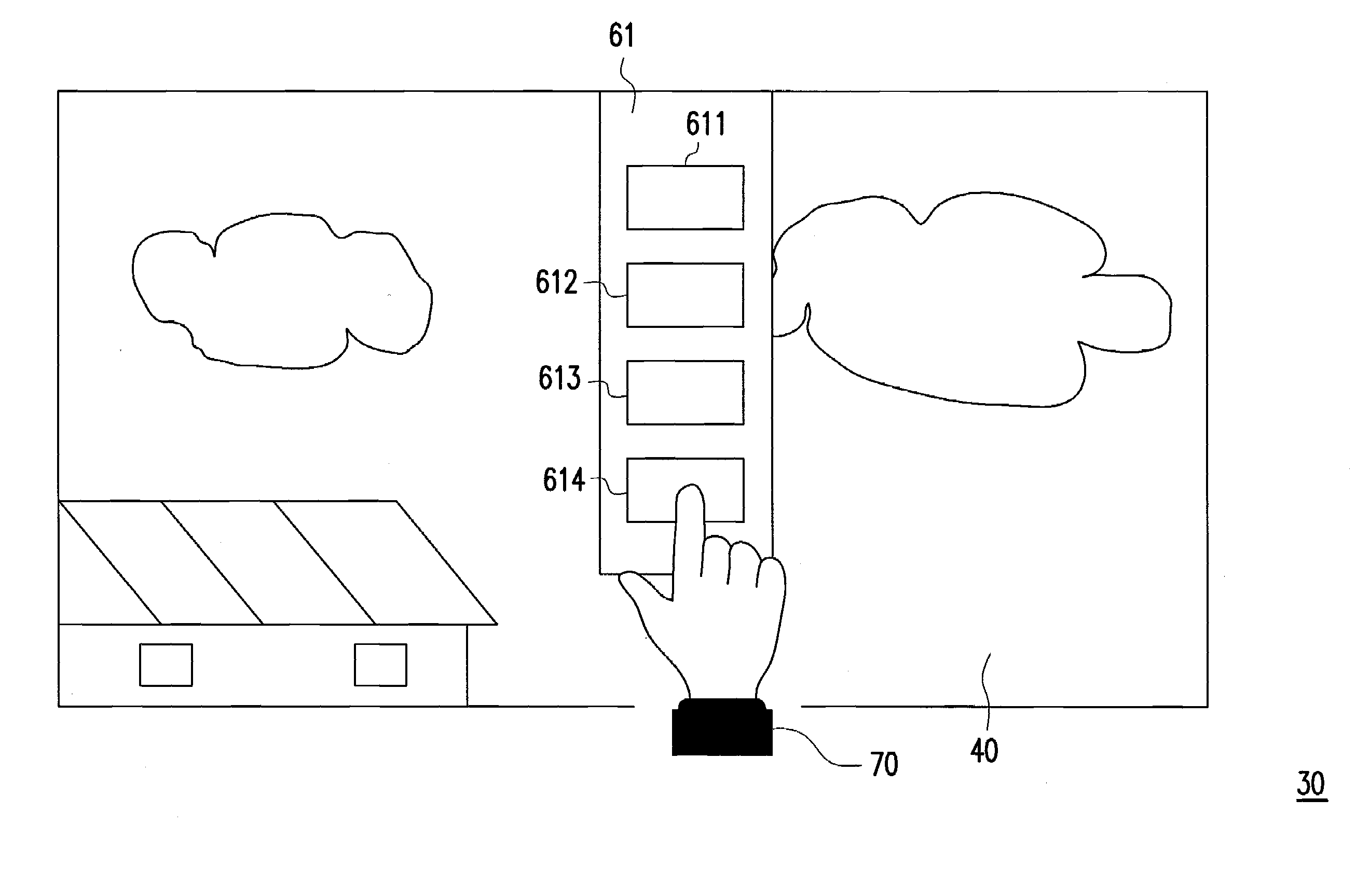
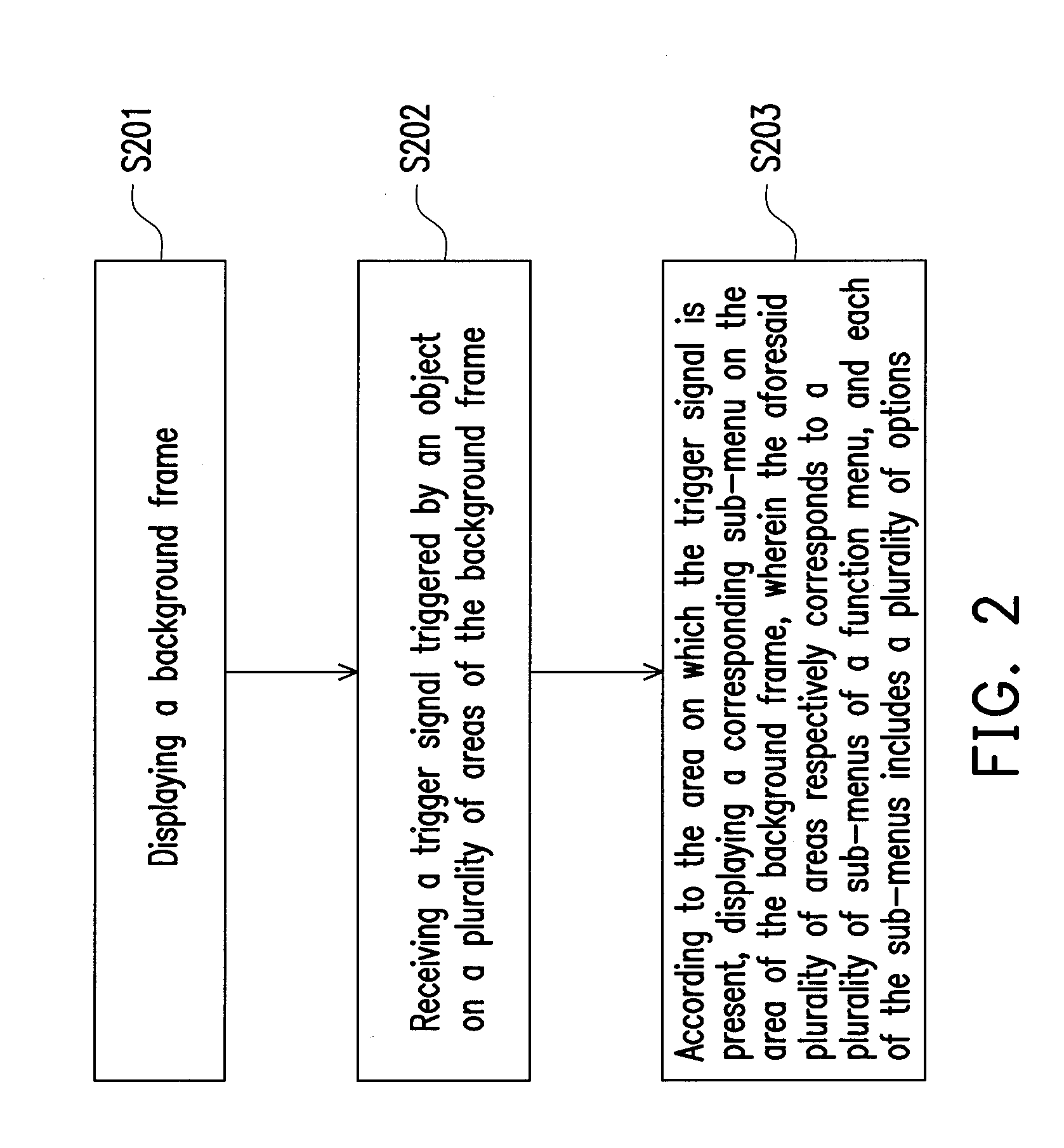
[0032]FIG. 2 is a flowchart showing a method for displaying and operating a user interface according to the first embodiment of the present invention. FIGS. 3A to 3C are schematic views showing a user interface according to the first embodiment of the present invention. Referring to all FIGS. 2 and 3A to 3C, first the background frame may be displayed on the user interface (a step S201). For example, clouds and houses may be displayed on a background frame 40 (as shown in FIG. 3A), but the present invention is not limited herein. According to other embodiments, persons having ordinary skills in the art may chose to display different background frames according to requirements thereof.

[0033]It should be noted that, the background frame may be divided into a plurality of areas, which respectively corresponds to a plurality of sub-menus of a function menu, and each of the sub-menus may include a plurality of options. For example, the aforesaid areas are areas 51 and 52 (as shown in FIG...

second embodiment

[0039]FIG. 4 is a flowchart showing a method for displaying and operating a user interface according to the second embodiment of the present invention. FIGS. 5A to 5F are schematic views showing a user interface according to the second embodiment of the present invention. Referring to all FIGS. 4 and 5A to 5F, first a background playing information may be set (a step S401). For example, a background frame 41 may be set to be displayed on a user interface 31. For example, a predetermined picture may be selected form a plurality of pictures to be an initial background frame 41. In addition, whether to enable a function of a digital photo album may be set, so as to change the background frame 41. Moreover, a playing mode of the digital photo album may be set. For example, one of the plurality of pictures may be randomly selected to be played, or one of the plurality of pictures may be selected to be played according to a sequence of names of the pictures.

[0040]Furthermore, a system inf...

third embodiment

[0050]FIG. 6 is a block diagram showing an electronic device according to the third embodiment of the present invention. Referring to FIG. 6, an electronic device 600 is, for example, a notebook computer, a PDA, a cellular phone or a multimedia player which includes a storage unit 610, a display unit 620, an input unit 630 and a controller 640. The controller 640 is respectively coupled to the storage unit 610, the display unit 620 and the input unit 630. The following introduces functions of each of components in the electronic device 600.

[0051]The storage unit 610 is, for example, a hard drive or a memory which may be used to store data, pictures or files. The display unit 620 is, for example, a monitor which is used to display a frame. The input unit 630 is, for example, a trackpad which is disposed on the display unit 620 and used for the user to operate the electronic device 600. In other words, the input unit 630 and the display unit 620 may be combined into the touch screen, ...


PUM


Abstract

A method for displaying and operating a user interface and an electronic device are provided. In the method, a background frame is displayed. Further, a trigger signal triggered by an object on one of a plurality of areas of the background frame is received, in which the areas respectively correspond to a plurality of sub-menus of a function menu, and each of the sub-menus includes a plurality of options. The corresponding sub-menu is displayed on the area of the background frame which the trigger signal is triggered on. Thereby, usage convenience of the user interface is improved.

Description

CROSS-REFERENCE TO RELATED APPLICATION[0001]This application claims the priority benefit of Taiwan application serial no. 97150767, filed on Dec. 25, 2008. The entirety of the above-mentioned patent application is hereby incorporated by reference herein and made a part of specification.BACKGROUND OF THE INVENTION[0002]1. Field of the Invention[0003]The present invention relates to a user interface, and particularly to a method for displaying and operating the user interface.[0004]2. Description of Related Art[0005]As technology advances, various sorts of electronic devices are continually developed, for example notebook computers, personal digital assistants (PDA) and cell phones. In order to enhance usage convenience of the electronic devices, prior art applies touch screens to the electronic devices. The touch screen can not only be used to display frames, but can also be used to operate the electronic device, so they are a kind of convenient tool.[0006]In detail, when the touch s...

Claims


Application Information

Patent Timeline
Patent Type & Authority Applications(United States)
IPC IPC(8): G06F3/048
CPCG06F3/0482G06F3/0488
Inventor CHANG, CHING-CHIH
Owner COMPAL ELECTRONICS INC
Why Eureka
Try Eureka