This helps you quickly interpret patents by identifying the three key elements:
Problems solved by technology
Method used
Benefits of technology
Benefits of technology
[0015]In one embodiment, the anvil assembly includes an anvil shaft extending proximally of the anvil head and removably mountable to an anvil retainer of the stapler. In one embodiment, the projections are integral with the anvil shaft and formed by angled cuts in the anvil shaft, the cuts preferably angling toward a distal end of the anvil shaft. In one embodiment, the cuts have a first dimension
Problems solved by technology
The staples interrupt the blood flow of the superior hemorrhoidal arterial br
Method used
Image
Click on the blue label to locate the original text in one second.
Reading with bidirectional positioning of images and text.
Examples
Embodiment Construction
[0031]The presently disclosed surgical stapler will now be described in detail with reference to the drawings in which like reference numerals designate identical or corresponding elements in each of the several views. Throughout this description, the term “proximal” will refer to the portion of the stapler closer to the operator and the term “distal” will refer to the portion of the instrument further from the operator. The presently disclosed stapler is particularly suited for surgical procedures for the treatment of colon prolapse and hemorrhoids, although it can be used for other procedures.
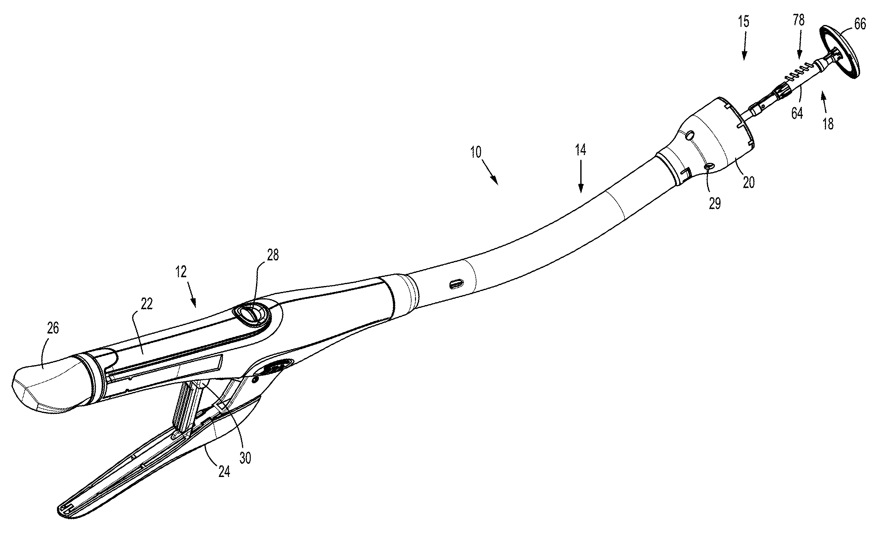
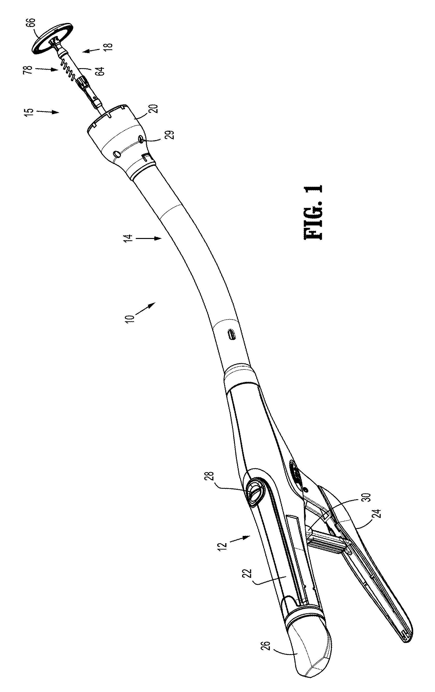
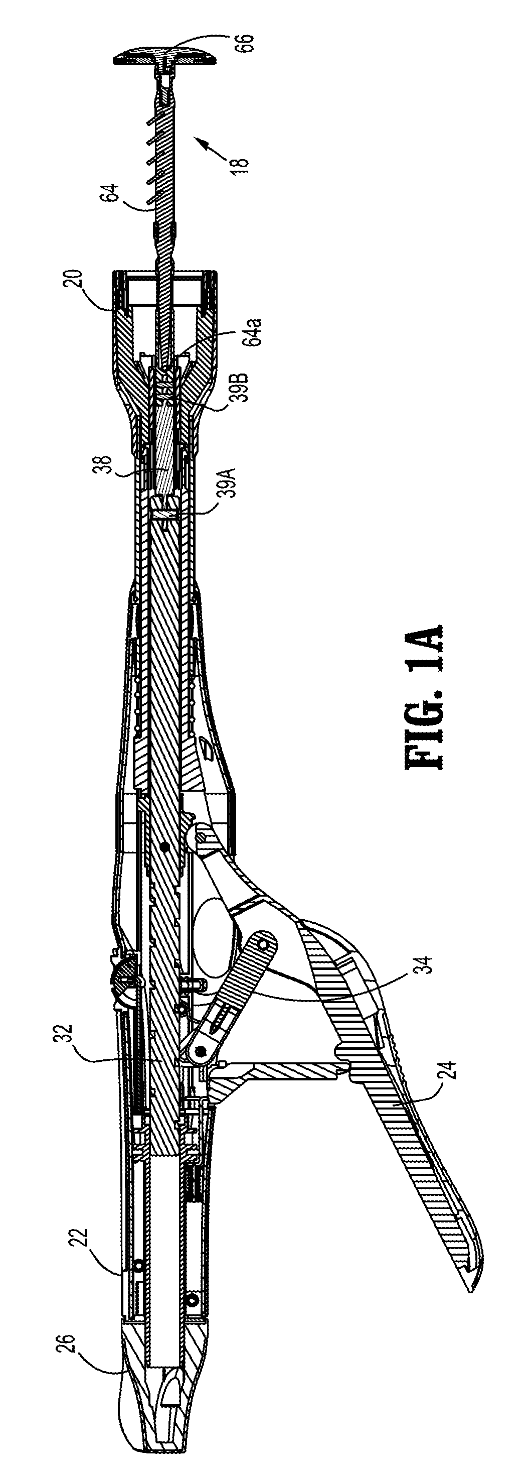
[0032]FIGS. 1 and 1A illustrate one embodiment of the presently disclosed hemorrhoid stapler 10. Briefly, surgical stapler 10 includes a handle assembly 12, a central body or elongated portion 14 and a distal head portion 15. Head portion 15 includes an anvil assembly 18 and a shell assembly 20. Except where otherwise noted, the components of stapler 10 are generally formed from thermoplastic...
PUM
Property
Measurement
Unit
Angle
aaaaa
aaaaa
Width
aaaaa
aaaaa
Dimension
aaaaa
aaaaa
Abstract
An anvil assembly comprising an anvil shaft and an anvil head, the anvil head having anvil depressions for forming surgical staples. The anvil head is mounted to the anvil shaft and the anvil shaft has a longitudinal axis and first and second spaced apart elongated projections attached to the anvil shaft and extending therefrom. The projections are configured and dimensioned to retain a purse string suture.
Description
[0001]This application claims priority from U.S. Provisional Application No. 61 / 142,660, filed Jan. 6, 2009, the entire contents of which are incorporated herein by reference.BACKGROUND[0002]1. Technical Field[0003]The present disclosure relates to a surgical stapling device and more particularly to a surgical stapling device suitable for treatment of internal hemorrhoids.[0004]2. Background of Related Art[0005]Anastomosis is the surgical joining of separate hollow organ sections. In known circular anastomosis procedures, two ends of organ sections are joined by means of a stapling device which drives a circular array of staples through each organ section and simultaneously cores any tissue interior of the driven circular array of staples to free a tubular passage. Examples of such devices are described in U.S. Pat. Nos. 7,234,624, 6,945,444, 6,053,390, 5,588,579, 5,119,983, 4,646,745, 4,576,167, 4,473,077.[0006]Typically the circular stapling device has an elongated shaft having a ...
Claims
Application Information
Patent Timeline
Application Date:The date an application was filed.
Publication Date:The date a patent or application was officially published.
First Publication Date:The earliest publication date of a patent with the same application number.
Issue Date:Publication date of the patent grant document.
PCT Entry Date:The Entry date of PCT National Phase.
Estimated Expiry Date:The statutory expiry date of a patent right according to the Patent Law, and it is the longest term of protection that the patent right can achieve without the termination of the patent right due to other reasons(Term extension factor has been taken into account ).
Invalid Date:Actual expiry date is based on effective date or publication date of legal transaction data of invalid patent.

