

Manufacturing method of a vehicular interior part
- Summary
- Abstract
- Description
- Claims
- Application Information
AI Technical Summary
Benefits of technology
Problems solved by technology
Method used
Image

Examples
Embodiment Construction
[0026]An illustrative example of the present invention is described in reference to FIGS. 1 to 11.
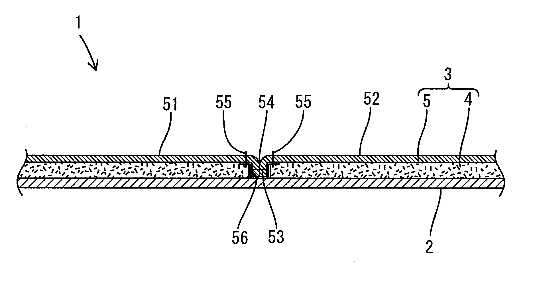
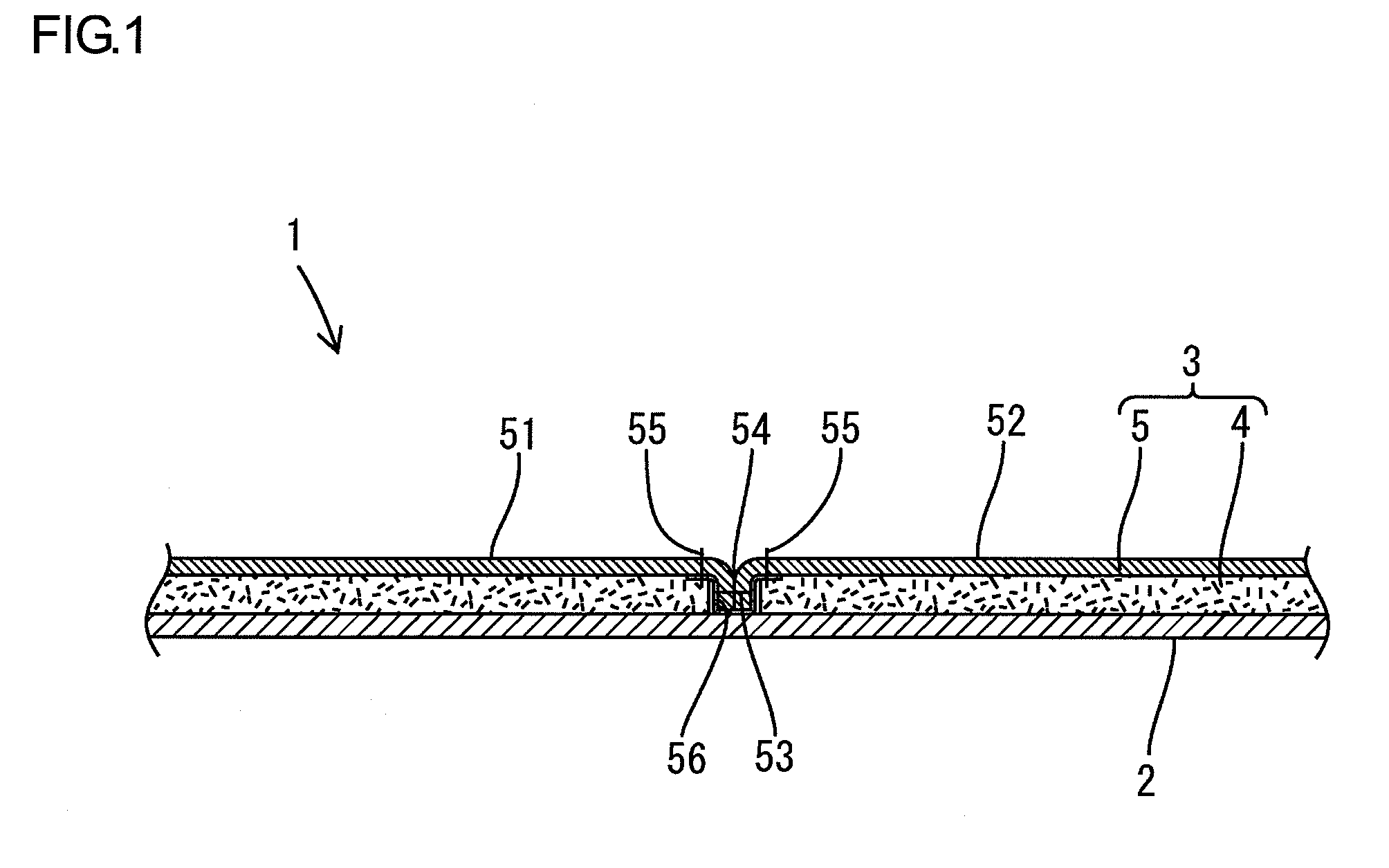
[0027]Referring to FIG. 1, a vehicular interior part according to the present illustrative example includes a base material 2 and a cover member 3 attached to a surface of the base material 2.
[0028]The base material 2 is an instrument panel of a vehicle. The base material 2 is integrally formed by resin such as polypropylene and is installed in front of a front seat or a driver's seat of the vehicle.
[0029]The cover member 3 includes a skin material 5 and a cushion material 4 attached to the backside of the skin material 5.
[0030]The skin material 5 includes a plurality of skin pieces 51 and 52 that are joined together by sewing. The plurality of skin pieces 51 and 52 are made of an animal skin (genuine leather) such as a cowhide, and are sewn together by a sewing thread 53.
[0031]The skin material 5 is formed in three dimensions in accordance with the surface shape of the base material 2....
PUM
| Property | Measurement | Unit |
|---|---|---|
| Length | aaaaa | aaaaa |
| Thickness | aaaaa | aaaaa |
Abstract
Description
Claims
Application Information