Oil pump for vehicle and vehicle with the same

Active Publication Date: 2014-11-20
TOYOTA JIDOSHA KK +1
View PDF7 Cites 3 Cited by
  • Summary
  • Abstract
  • Description
  • Claims
  • Application Information

AI Technical Summary

Benefits of technology

The oil pump described in this patent has a plate that can be placed between the rear cover and pump body, which creates a cavity where oil can flow. This eliminates the need for separate passages for the rear cover and pump body. The plate, control valve, and pump cover can all be combined into one module, which can be mounted on the rear cover for easy checking and quality assurance. This also eliminates the need for hydraulic or air pressure to check valve actuation.

Problems solved by technology

This limits flexibility in disposing an oil passage between the rear cover and the pump body.
If the independent oil passage is provided with the rear cover or the pump body, for example, the rear cover or the pump body may increase in production cost.

Method used


Image

  • Oil pump for vehicle and vehicle with the same
  • Oil pump for vehicle and vehicle with the same
  • Oil pump for vehicle and vehicle with the same

Examples


Embodiment Construction

[0023]A description will be given of an embodiment of the present invention in detail below by referring to the accompanying drawings. In the following embodiment, the drawings are simplified or modified as needed for ease of understanding. A dimensional ratio, a shape, and a similar parameter of each part depicted in the drawings are not necessarily accurate.

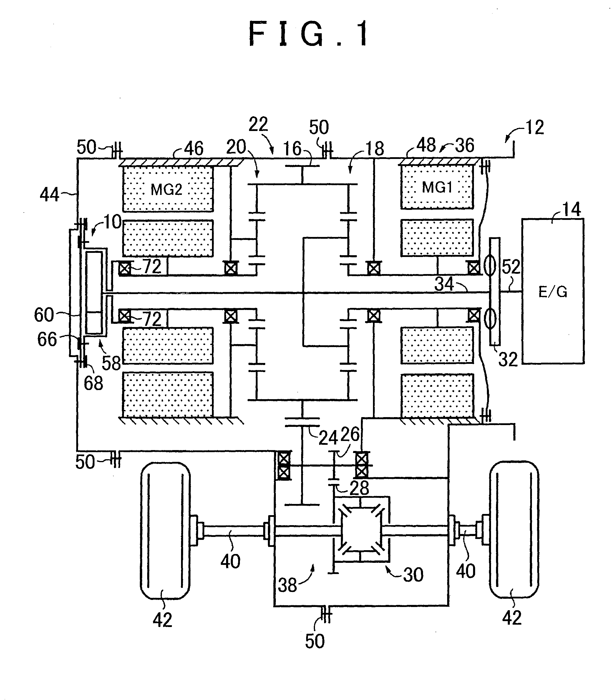
[0024]FIG. 1 is a diagram illustrating a schematic configuration of a hybrid vehicle 12 (hereinafter referred to as a vehicle 12) including an oil pump 10 for vehicle according to an embodiment of the present invention.

[0025]In FIG. 1, the vehicle 12 includes a transmission part 22. The transmission part 22 includes a power distribution mechanism 18 (a differential mechanism), a gear mechanism 20, and a second electric motor (an electric motor) MG2. The power distribution mechanism 18 distributes power, which is output from an engine 14 as a driving force source for running, to a first electric motor MG1 and an output gear 16. ...


PUM


Abstract

A plate is interposed between a rear cover and a pump body. The pump chamber is formed between the plate and the pump body.

Description

BACKGROUND OF THE INVENTION[0001]1. Field of the Invention[0002]This invention relates to an oil pump for vehicle with a pump body that is secured to a rear cover of a transaxle case and a vehicle with the oil pump.[0003]2. Description of Related Art[0004]As disclosed in Japanese Patent Application Publication No. 2002-70753 (JP 2002-70753 A), the oil pump for vehicle is disposed, for example, at an input side of a transaxle. The oil pump for vehicle disclosed in JP 2002-70753 A includes a driven gear, a drive gear that engages the driven gear, and a pump chamber that houses the driven gear and the drive gear.[0005]In contrast, some oil pumps for vehicle are disposed on the opposite side of the input side of the transaxle, that is, on a rear cover side of the transaxle case. Such oil pump for vehicle includes, for example, a pump chamber formed between the rear cover and a pump body secured to the rear cover. Additionally, the oil pump includes the driven gear and the drive gear tha...

Claims


Application Information

Patent Timeline
IPC IPC(8): F04C2/00F04C28/24
CPCF04C28/24F04C2/00F04C2/086F04C2210/206F04C2/102F04C14/24F04C14/26B60K6/405F16H57/0476B60K17/12F16H57/0486
Inventor OBATA, TATSUOKIMURA, HIROMICHIKUWAHARA, TAKESHIKITAGAWA, KATSUHIDEMORISAWA, KUNIOSENO, MASAMITSUYATA, HIROTAKAATARASHI, TOMOO
Owner TOYOTA JIDOSHA KK
Why Eureka
Try Eureka