Eureka AIR delivers breakthrough ideas for toughest innovation challenges, trusted by R&D personnel around the world.

Ink containment system for an ink-jet pen

Inactive Publication Date: 2005-05-10
HEWLETT PACKARD DEV CO LP
View PDF5 Cites 13 Cited by
  • Summary
  • Abstract
  • Description
  • Claims
  • Application Information

AI Technical Summary

Benefits of technology

[0008]To control leakage, extra felting of the foam member has been employed. Felting is a measure of the extent to which foam is compressed. Compressing the foam decreases the pore dimensions. By increasing the felting of the foam (i.e., the amount of compression of the foam), pore size decreases and capillary force increases. A greater capillary force increases back pressure within the reservoir. An increase in back pressure within the reservoir helps to prevent drool. However, extra felting of the foam does not aid removal of air trapped within the foam. Extra felting also reduces the foam's ink storage capacity. Moreover, extra felting makes manufacturing difficult, as the foam is difficult to insert in the necessarily small reservoir.
[0009]Grooved reservoir walls have been used to prevent ink drool. The grooves create a series of interconnected channels between the foam member and the reservoir walls. Expanding air from the foam's interior diffuses into these channels and is vented out of the reservoir. However, the grooved reservoir walls can be difficult to manufacture. Additionally, grooved reservoir walls can make the walls more flexible, and the pressure exerted by the compressed foam can deform the flexible reservoir walls so that the ink-jet pen does not fit properly within the printer.
[0010]The present invention is directed to a system for storing ink in a pen reservoir, while preventing ink leakage due to a change in ambient temperature or pressure. The system comprises porous grooved foam. The porous foam is grooved on the exterior portion to provide paths for air to move to the atmosphere. Thus, air within the interior portion of the foam may expand to the grooves on the exterior portion. An atmospheric vent is in fluid communication with at least one of the grooves, thereby to vent excess air within the reservoir. The grooved foam may be used in any of a variety of ink-jet pen reservoirs and may be implemented with any foam-based pen.

Problems solved by technology

Excess ink delivery leads to leakage, or drooling from the nozzles.
Unless this expansion is managed, the displaced ink is forced out the printhead nozzles resulting in undesired drool.
The mixing of these two ink colors causes contamination, producing poor quality printing.
However, substantially all of the exterior surfaces of conventional foam ink storage members are in contact with the walls of the pen reservoir.
When changes in ambient conditions occur to expand air in the reservoir, the expanded trapped air displaces ink and causes drool through the nozzles.
However, extra felting of the foam does not aid removal of air trapped within the foam.
Extra felting also reduces the foam's ink storage capacity.
Moreover, extra felting makes manufacturing difficult, as the foam is difficult to insert in the necessarily small reservoir.
However, the grooved reservoir walls can be difficult to manufacture.
Additionally, grooved reservoir walls can make the walls more flexible, and the pressure exerted by the compressed foam can deform the flexible reservoir walls so that the ink-jet pen does not fit properly within the printer.

Method used


Image

  • Ink containment system for an ink-jet pen
  • Ink containment system for an ink-jet pen
  • Ink containment system for an ink-jet pen

Examples


Embodiment Construction

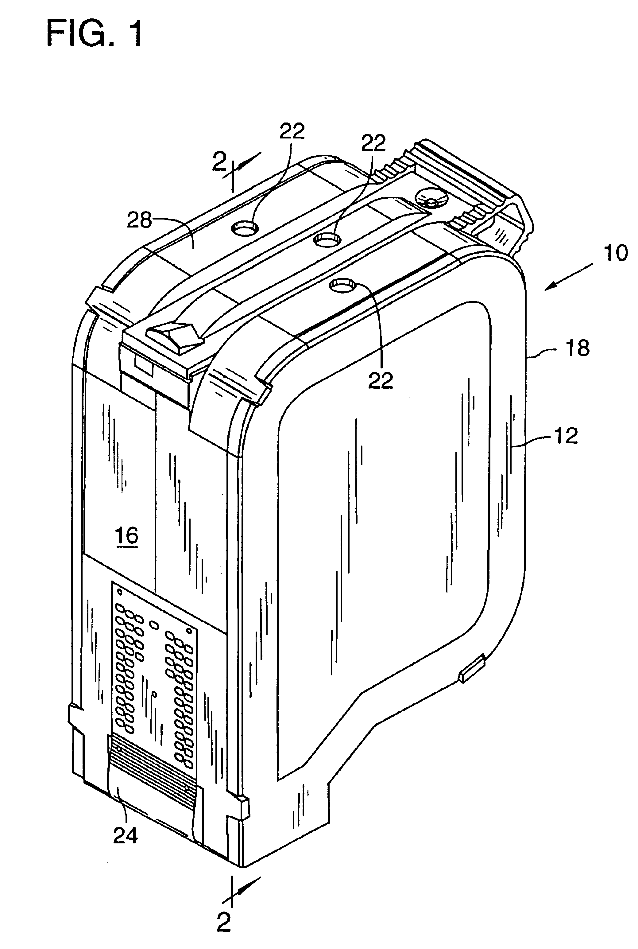
[0021]FIG. 1 shows a three-color ink-jet cartridge 10 having a box shaped body 12. A printhead 20 is attached to the bottom of the pen body 12 (FIG. 2). The printhead 20 defines three separate sets of print orifices (not shown) that provide apertures for expelling ink in a controlled pattern during printing. The printhead 20 is electronically controlled through a connector circuit 24 mounted on the body 12.

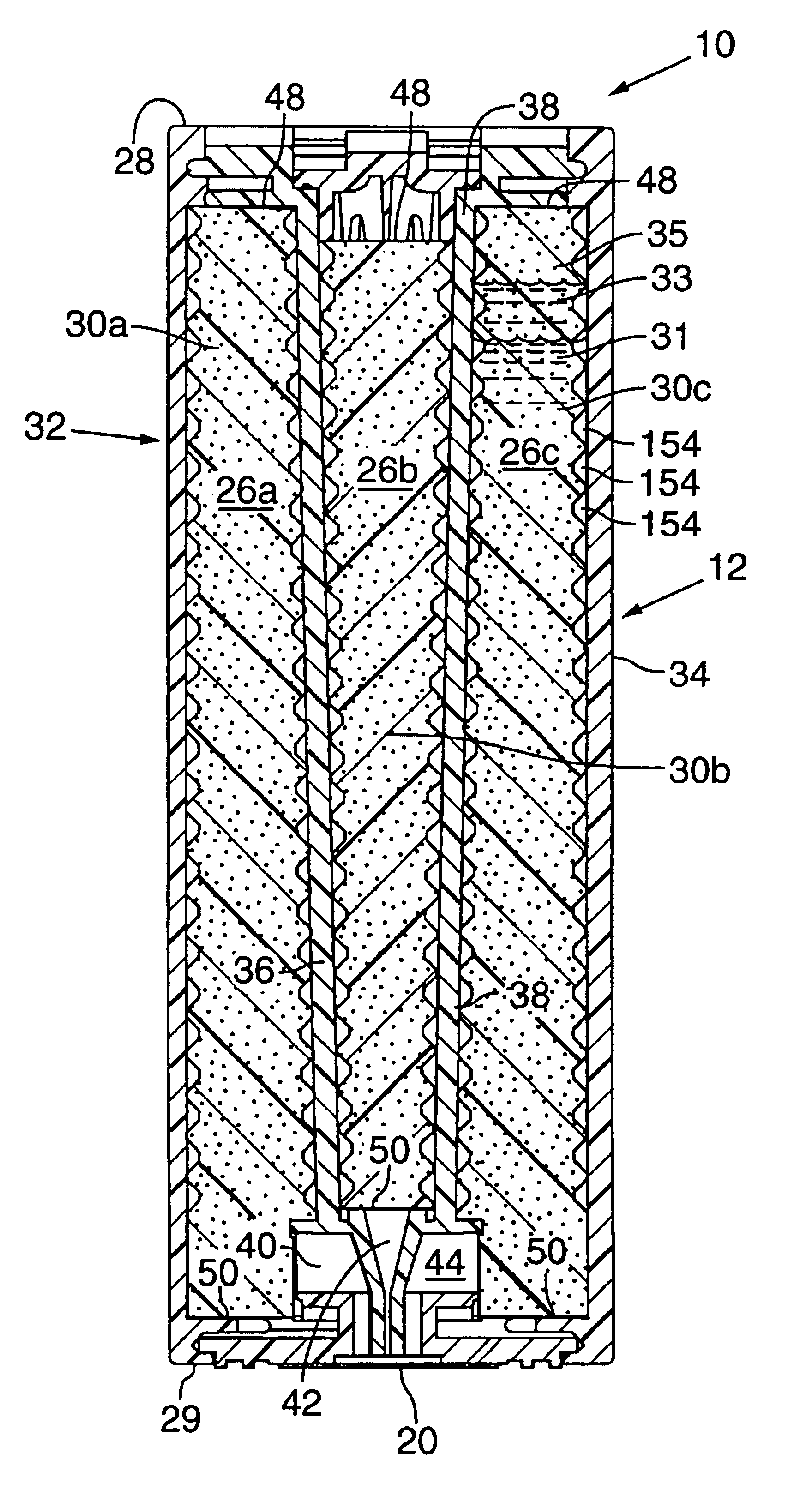
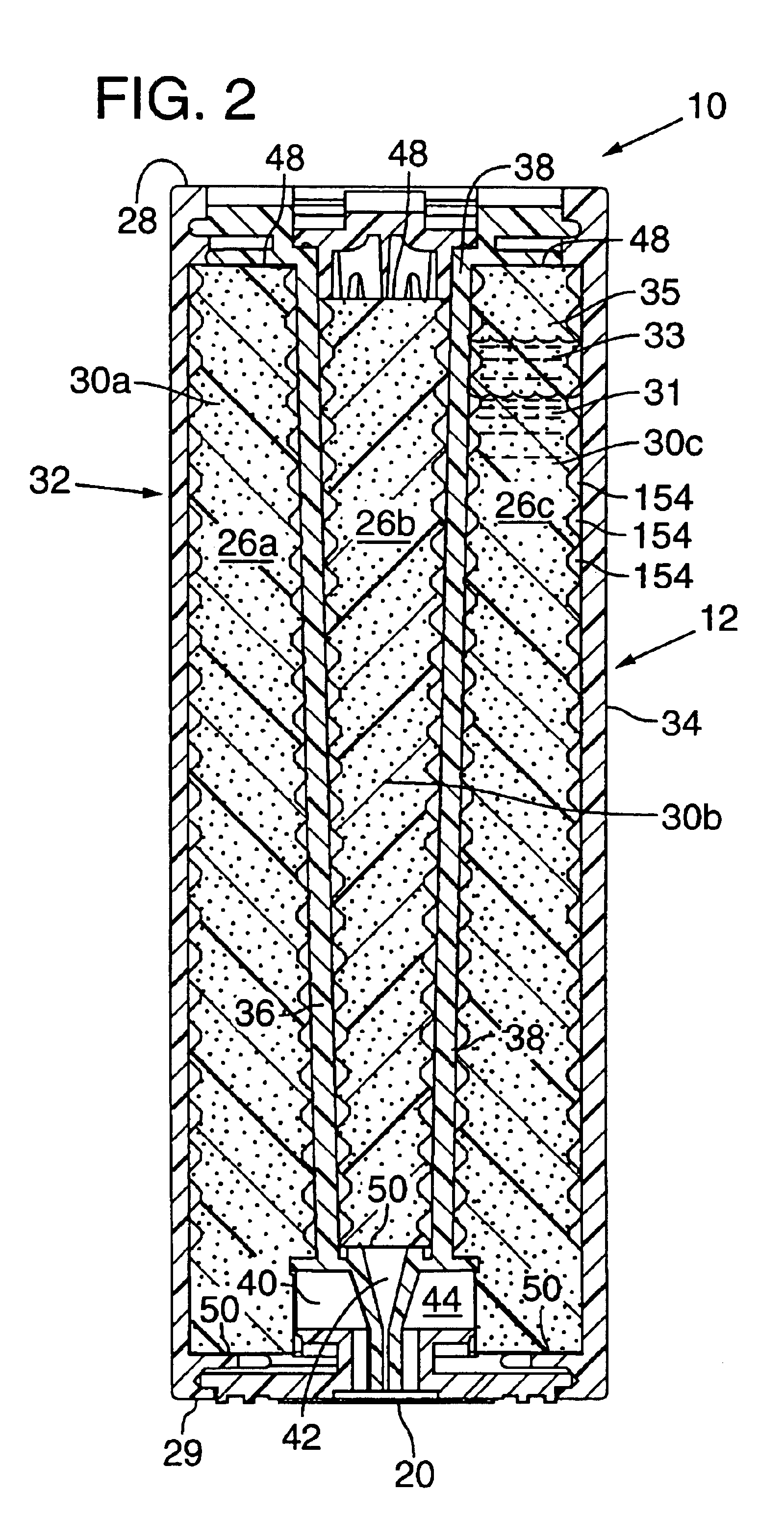
[0022]Referring to FIG. 2, the body 12 defines three similar sized adjacent ink chambers 26a, 26b, 26c, (also referred to herein as reservoirs). On each side of the cartridge 10 there is a side cover 32, 34 each of which forms a respective wall of ink chambers 26a and 26c. The pen body 12 includes interior walls 36 and 38, which partially define ink chamber 26b and serve as the interior walls for ink chambers 26a and 26c.

[0023]Each ink chamber 26a, 26b, 26c is connected to ink outlets 40, 42, 44, respectively (FIG. 2). Each ink outlet is fluidly coupled to its associated set of p...


PUM


Abstract

A porous foam based ink containment system is provided with grooves defined in the exterior portion thereof, for storing ink, while preventing ink leakage from the ink-jet pen. The grooves provide passageways to allow air diffused throughout the ink and trapped air bubbles within the foam to expand and move to the atmosphere. An atmospheric vent is in fluid communication with at least one of the grooves.

Description

CROSS REFERENCE TO RELATED APPLICATION[0001]This is a continuation of application Ser. No. 08 / 548,568 filed on Oct. 26, 1995, now abandoned which is hereby incorporated by reference herein.TECHNICAL FIELD[0002]The present invention is directed to a foam-based ink containment system for an ink-jet printer.BACKGROUND AND SUMMARY OF THE INVENTION[0003]An ink-jet printer includes a pen in which small droplets of ink are formed and ejected from the printer pen toward a printing medium. Such pens include printheads with orifice plates with several very small nozzles through which the ink droplets are ejected. Adjacent to the nozzles are ink chambers, where ink is stored prior to ejection through the nozzle. Ink is delivered to the ink chambers through ink channels in fluid communication with an ink supply. The ink supply may be, for example, contained in a reservoir part of the pen.[0004]For color printing, multiple colors are made available to the printer. For each color of ink there is ...

Claims


Application Information

Patent Timeline
IPC IPC(8): B41J2/175
CPCB41J2/17513B41J2/17556B41J2/17553B41J2/17526
Inventor KAWAMURA, NAOTOWEBER, TIMOTHY L.
Owner HEWLETT PACKARD DEV CO LP
Why Eureka
Eureka Blog
Learn More