One Piece Prosthetic Valve Support Structure and Related Assemblies

a support structure and prosthetic technology, applied in the field of one-piece mitral valve prosthesis, can solve the problems of increased cardiac events and death, inability to design, increased risk of death, etc., and achieve the effect of effective and reliable delivery of valve prosthesis

Inactive Publication Date: 2010-07-08
ENDOVALVE
View PDF51 Cites 182 Cited by
  • Summary
  • Abstract
  • Description
  • Claims
  • Application Information

AI Technical Summary

Benefits of technology

[0021]In use, the disclosed support structure permits a clinician to deliver, position and release a valve prosthesis in situ. The support structure is generally defined by applying the requisite cuts to a tubular member formed of a shape memory metal, e.g., Nitinol. Thereafter, the tubular member is deflected/expanded so as to assume a desired expanded configuration, i.e., to define the disclosed “support structure” a mounting collar, support struts, support ring and retention clip elements are in their desired relative orientation, and the shape memory metal/Nitinol is processed so as to “retain” such expanded configuration in memory. Thereafter, the support structure may be collapsed into a substantially tubular orientation, e.g., for trans-catheter delivery, and retained in such collapsed configuration, e.g., by placement within a...

Problems solved by technology

Mitral regurgitation due to ischemic and degenerative (prolapse) disease has been shown to contribute to left ventricular dilation and dysfunction due to remodeling, and is associated with increased rates of cardiac events and death.
Currently, malfunctioning heart valves may be replaced with biologic or mechanical prostheses through open-heart surgery with the attendant significant risk of death, stroke, infection, bleeding, and complications due to the use of general anesthesia and cardiopulmonary bypass.
Such a design is not amenable to placement of the heart valve prosthesis at the location of the biologic valve.
It is also difficult to position these designs as one has to inflate a balloon in a moving column of blood...

Method used


Image

  • One Piece Prosthetic Valve Support Structure and Related Assemblies
  • One Piece Prosthetic Valve Support Structure and Related Assemblies
  • One Piece Prosthetic Valve Support Structure and Related Assemblies

Examples


Embodiment Construction

)

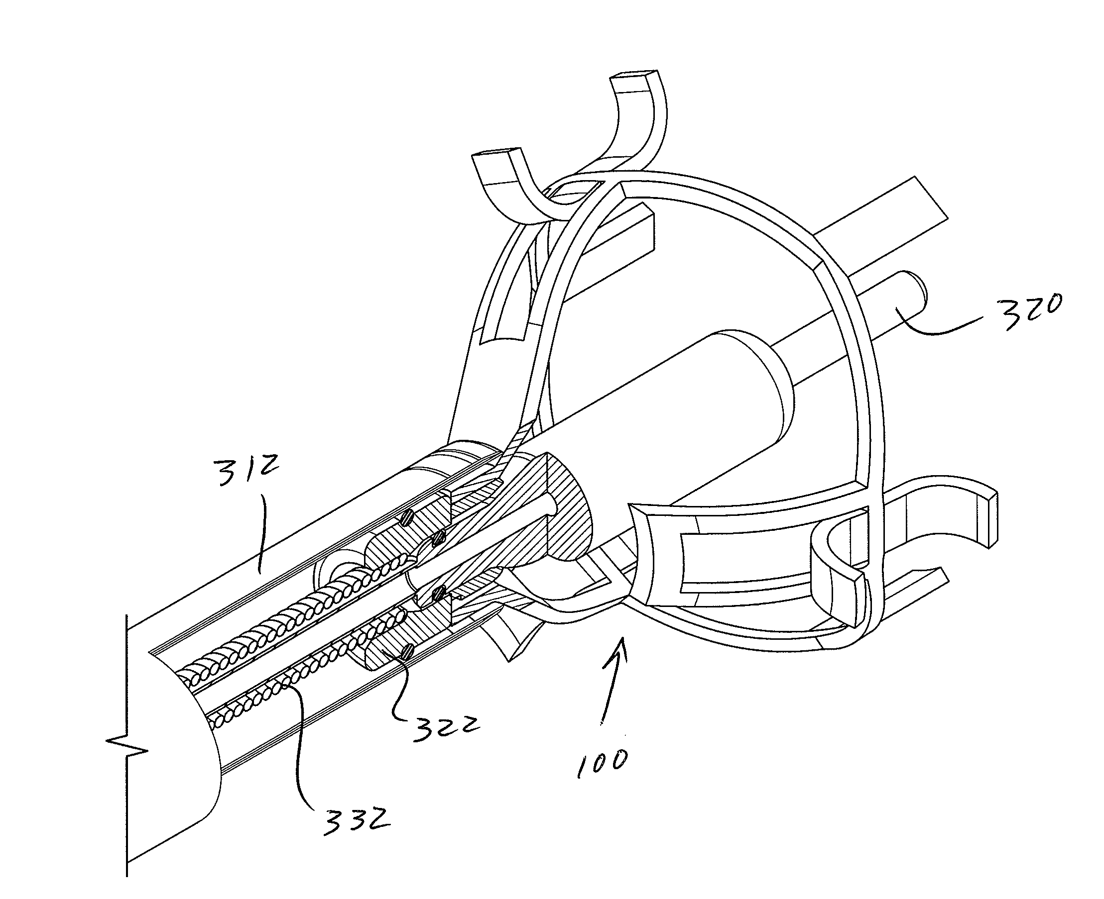
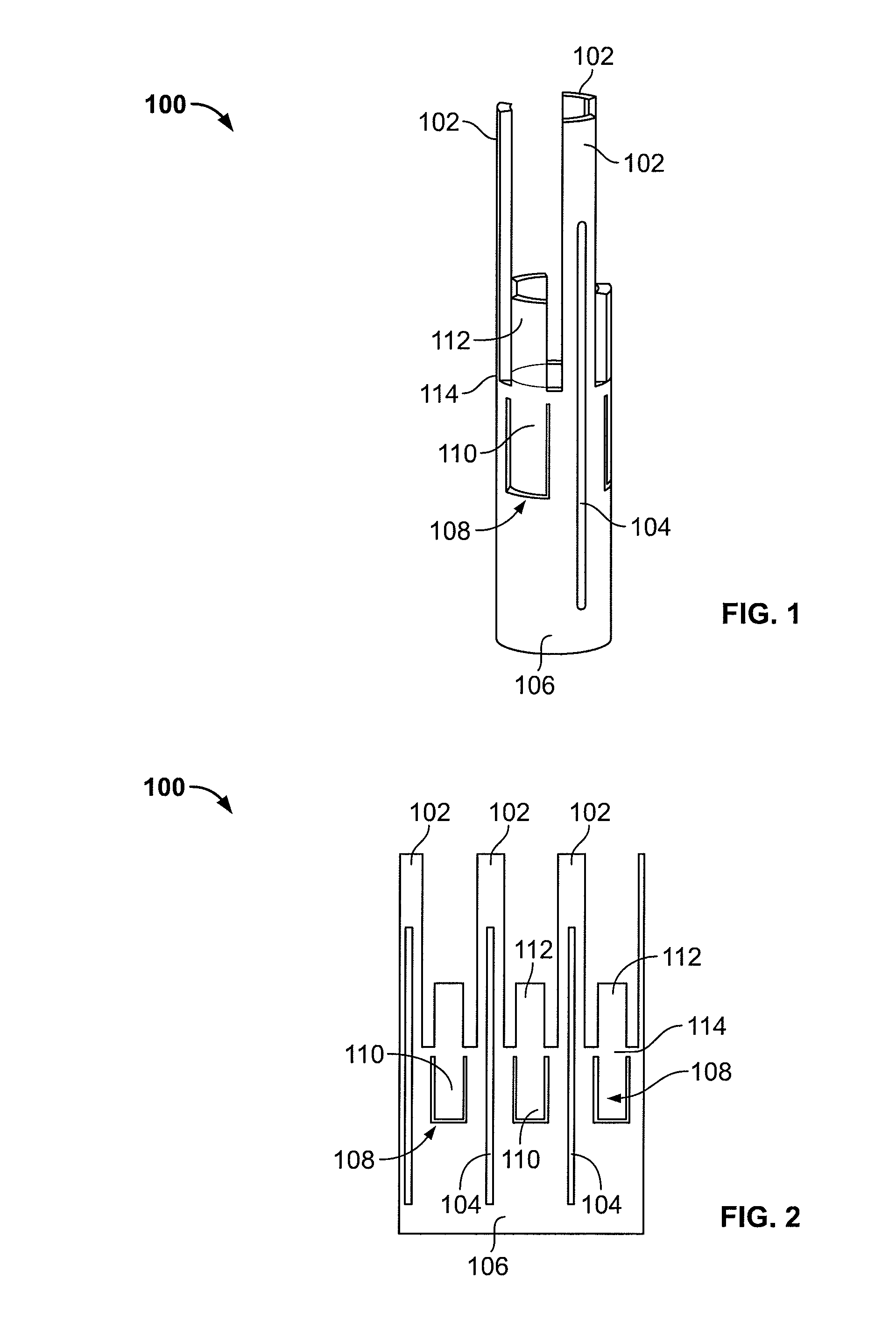
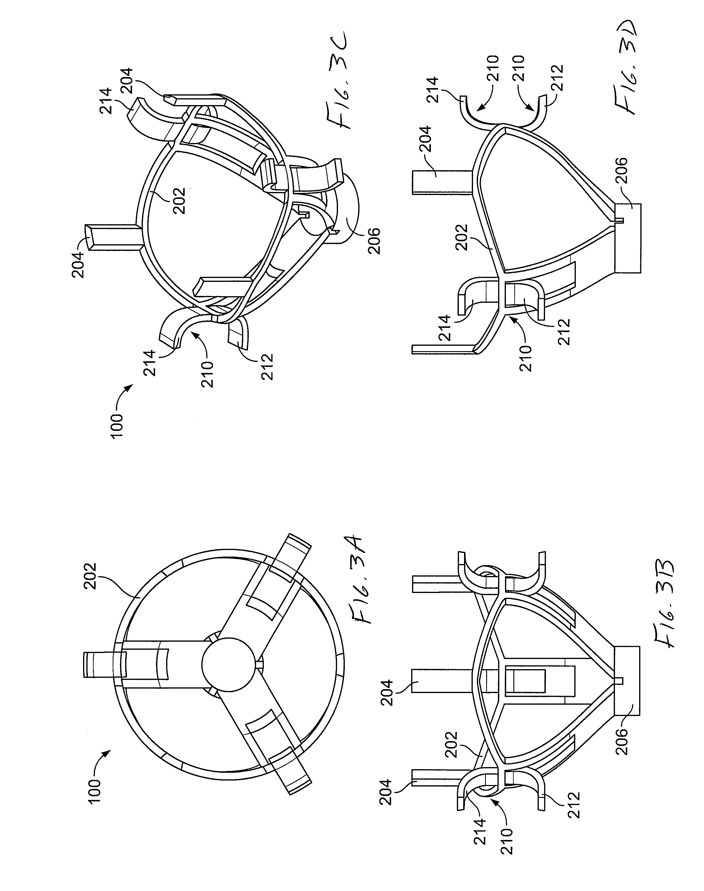
[0030]Advantageous valve support structures, valve prosthesis systems and deployment systems / methods are provided according to the present disclosure. The disclosed systems and methods permit surgeons / clinicians to improve heart valve function without invasive surgical intervention. Indeed, the disclosed valve prosthesis systems permit a heart valve prosthesis to be percutaneously delivered to a desired anatomical location. Once located in the desired anatomical region / locale, the disclosed valve prosthesis system facilitates secure and aligned placement of a heart valve prosthesis relative to a heart annulus. Percutaneous delivery of the disclosed heart valve prosthesis as disclosed herein provides for efficient and effective clinical placement of a heart valve prosthesis. The disclosed heart valve prosthesis and associated delivery techniques offer numerous clinical benefits, including enhanced valve function without the need to remove existing valve leaflets, an ability to effec...


PUM

PropertyMeasurementUnit
Shape memory effectaaaaaaaaaa
Memory effectaaaaaaaaaa

Abstract

Valve prostheses are disclosed that are adapted for secure and aligned placement relative to a heart annulus. The valve prostheses may be placed in a non-invasive manner, e.g., via trans-catheter techniques. The valve prosthesis may include a support ring, a plurality of leaflet membranes mounted with respect to the support ring, and a plurality of retention clip elements. The support structure is advantageously formed from a tubular member or flat stock of shape memory metal. A delivery system for delivery of a valve prosthesis embodying the disclosed support structure is also disclosed.

Description

CROSS-REFERENCE TO RELATED APPLICATION[0001]The present application claims priority benefit to a co-pending provisional application entitled “One Piece Prosthetic Valve Support Structure and Related Assemblies” which was filed on Jan. 7, 2009 and assigned Ser. No. 61 / 142,975. The entire content of the foregoing provisional patent application is incorporated herein by reference.BACKGROUND [0002]1. Technical Field[0003]The present disclosure is directed to advantageous valve prosthesis systems and associated methods / systems for placement of a heart valve prosthesis and, more particularly, to a one-piece mitral valve prosthesis that is adapted for secure and aligned placement relative to a heart annulus and associated methods / systems for placement thereof[0004]2. Background Art[0005]Heart valve regurgitation occurs when the heart valve does not close completely as a result of disease or injury. Mitral regurgitation due to ischemic and degenerative (prolapse) disease has been shown to c...

Claims


Application Information

Patent Timeline
IPC IPC(8): A61F2/24B23P13/04
CPCA61F2/2418A61F2/2436Y10T29/49995A61F2220/0058A61F2220/005
Inventor CASTRO, SALVATORE
Owner ENDOVALVE
Why Eureka
Try Eureka