Dual-view stereoscopic display using linear modulator arrays

a stereoscopic display and linear modulator technology, applied in the field of display equipment, can solve the problems of additional requirements for inability to meet the requirements of robust display equipment, and inability to meet the requirements of theater design and layout,

Inactive Publication Date: 2010-07-15
EASTMAN KODAK CO
View PDF28 Cites 49 Cited by
  • Summary
  • Abstract
  • Description
  • Claims
  • Application Information

AI Technical Summary

Benefits of technology

[0026]It is an advantage of the present invention that it provides dual-view stereoscopic imaging from a single projection display apparatus.
[0027]These and other aspects, objects, features and advantages of the present invention will be more clearly understood and appreciated from a review of the following detailed description of the preferred embodiments and appended claims, and by reference to the accompanying drawings.

Problems solved by technology

However, proposed solutions for using laser light sources for digital projection fall short of what is needed for providing robust display apparatus that take advantage of this potential.
Although such two-projector designs have successfully shown the feasibility and enhanced imaging capabilities afforded by stereoscopic imaging systems, these systems are expensive, require precision alignment to each other, and impose some additional requirements on theater design and layout that complicate retrofit installation.
However, because they must direct light from the same projection lens, single-projector systems inherently tend to be less efficient.
While this approach may provide different stereoscopic views of an object for individual viewers, however, it requires filter glasses that are highly selective and costly.
Moreover, perfect spectral separation is not possible, so that there can be some crosstalk between viewers.
Although the value of providing dual-view stereo viewing capability is recognized, conventional approaches for achieving this have proved less than satisfactory.
For example, image crosstalk would be highly unfavorable for dual-view imaging.
'775 disclosure do not have the capability to support dual-view stereoscopic imaging in which two viewers are presented with different image content and the image presentation for each viewer is stereoscopic.
Other approaches struggle to provide sufficient brightness even with dual-view or stereoscopic imaging.
Extending these approaches to the requirements of dual view stereoscopic imaging would not provide a satisfactory viewing experience.

Method used


Image

  • Dual-view stereoscopic display using linear modulator arrays
  • Dual-view stereoscopic display using linear modulator arrays
  • Dual-view stereoscopic display using linear modulator arrays

Examples


embodiment 3

[0101]Embodiments E3 and E4 shown in FIG. 13 use spectral band differences to display stereo images with different timing. Embodiments E3 and E4 may use the apparatus shown in FIG. 12 without the optional striped polarization modifiers 40r, 40g, and 40b. Each of the bilinear GEMS device pairs would have 1080 pixels and receive light of one spectral band S1 or S2 used for separating left- and right-eye stereoscopic images. In Embodiment 3, during the first half of the image refresh cycle the left-eye image for the first set of viewers (A) is displayed using spectral band S1 while the right-eye image of the first set of viewers (A) is blocked and the right-eye image for the second set of viewers (B) is displayed using spectral band S2 while the left-eye image for the second set of viewers (B) is blocked. During the second half of the image refresh cycle, the right-eye image for the first set of viewers (A) is displayed using spectral band S2 while the left-eye image for the first set ...

embodiment 5

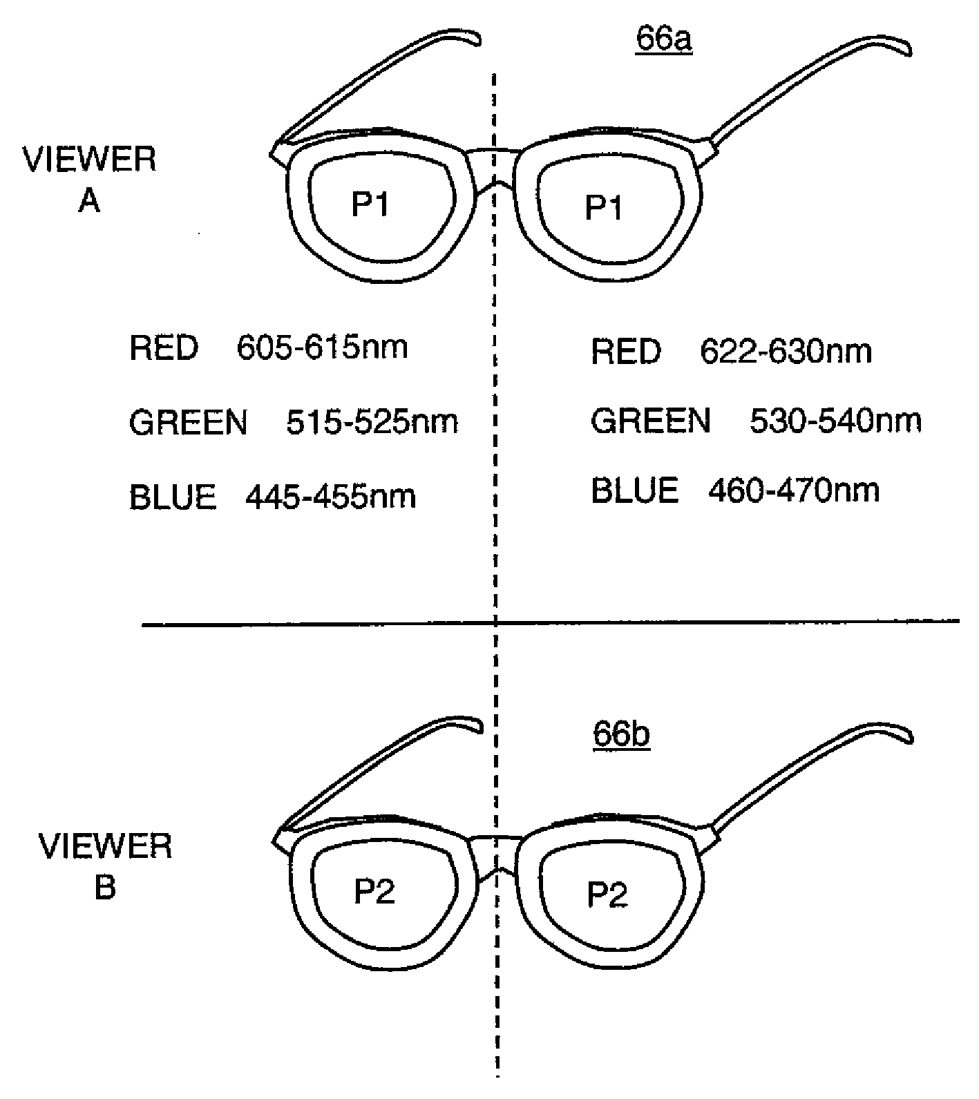
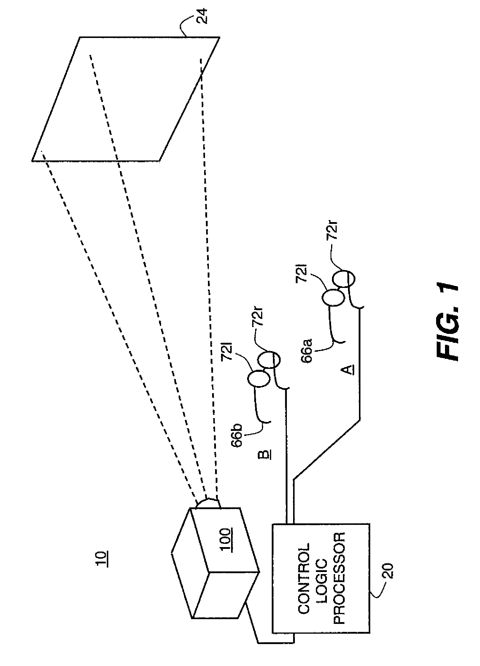
[0102]Embodiment E5 shown in FIG. 13 uses the apparatus in FIG. 5 with the dual spectral band light source arrangement of FIG. 9. As in embodiments E1 and E2 the GEMS device may have 2160 pixels in order to display the equivalent of 1080 pixels, with the odd-numbered pixels passing polarization P1 and the even-numbered pixels passing orthogonal polarization P2. Embodiment 5 uses polarization to distinguish left-eye and right-eye stereoscopic pairs for each set of viewers while using spectral band variation for timing to alternate between eyes. During the first half of an image refresh cycle, light source S1 is on and light source S2 is off; during the second half of an image refresh cycle, light source S2 is on and S1 is off. During the first half of an image refresh cycle, the decoding devices for each of the first set of viewers (A) transmit light from light source S1 to the left eyes of the first set of viewers (A) while blocking light from light source S1 to the right eyes of th...


PUM


Abstract

A method for displaying first and second stereoscopic images to first and second viewers provides the first viewer with a first decoding device having a first viewer differentiating element for receiving the first stereoscopic image and further having a first left- and right-eye differentiating elements for separating left- and right-eye images. The second viewer is provided with a second decoding device having a second viewer differentiating element for receiving the second stereoscopic image and further having a second left- and right-eye differentiating element. The first stereoscopic image is displayed to the first viewer by forming a first left-eye image and forming a first right-eye image, each over substantially half of the refresh period. The second stereoscopic image is displayed to the second viewer by forming a second left-eye image and forming a second right-eye image, each over substantially half of the refresh period.

Description

CROSS REFERENCE TO RELATED APPLICATIONS[0001]Reference is made to commonly-assigned copending U.S. patent application Ser. No. 11 / 950,488, filed Dec. 5, 2007, entitled DISPLAY APPARATUS USING BILINEAR ELECTROMECHANICAL MODULATOR, by Agostinelli et al.; U.S. patent application Ser. No. 12 / 047,605, filed Mar. 13, 2008, entitled STEREOSCOPIC DISPLAY USING MULTILINEAR ELECTROMECHANICAL MODULATOR, by Marcus et al., and U.S. patent application Ser. No. 12 / 116,467, filed May 7, 2008, entitled DISPLAY USING BIDIRECTIONALLY SCANNED LINEAR MODULATOR by Marcus et al.; the disclosures of which are incorporated herein.FIELD OF THE INVENTION[0002]This invention generally relates to display apparatus and more particularly relates to a display apparatus for dual-view stereoscopic presentation using an arrangement of linear electromechanical grating devices.BACKGROUND OF THE INVENTION[0003]With continuing improvements in cost and performance, solid-state lasers have potential benefits as illuminatio...

Claims


Application Information

Patent Timeline
Patent Type & Authority Applications(United States)
IPC IPC(8): H04N13/04G02B30/25
CPCG02B27/2264H04N2013/0463H04N13/0438H04N2013/403H04N13/341G02B30/24
Inventor MARCUS, MICHAEL A.AGOSTINELLI, JOHN A.
Owner EASTMAN KODAK CO
Why Eureka
Try Eureka