Switch device

a technology of switching device and switch, which is applied in the direction of electronic switching, piezoelectric/electrostrictive/magnetostrictive devices, pulse techniques, etc., can solve problems such as unusable, and achieve the effects of convenient and user-friendly operation, convenient and convenient switching, and low cost and compact structur

Active Publication Date: 2010-07-22
HUF HULSBECK & FURST GMBH & CO KG
View PDF8 Cites 7 Cited by
  • Summary
  • Abstract
  • Description
  • Claims
  • Application Information

AI Technical Summary

Benefits of technology

[0003]The invention creates a switching device for switching a consumer on and off such that the aforementioned disadvantages are avoided, and, in particular, p

Problems solved by technology

One disadvantage with such ignition switches is that they are not very user friendly because of the long insertion

Method used


Image

  • Switch device
  • Switch device
  • Switch device

Examples


Embodiment Construction

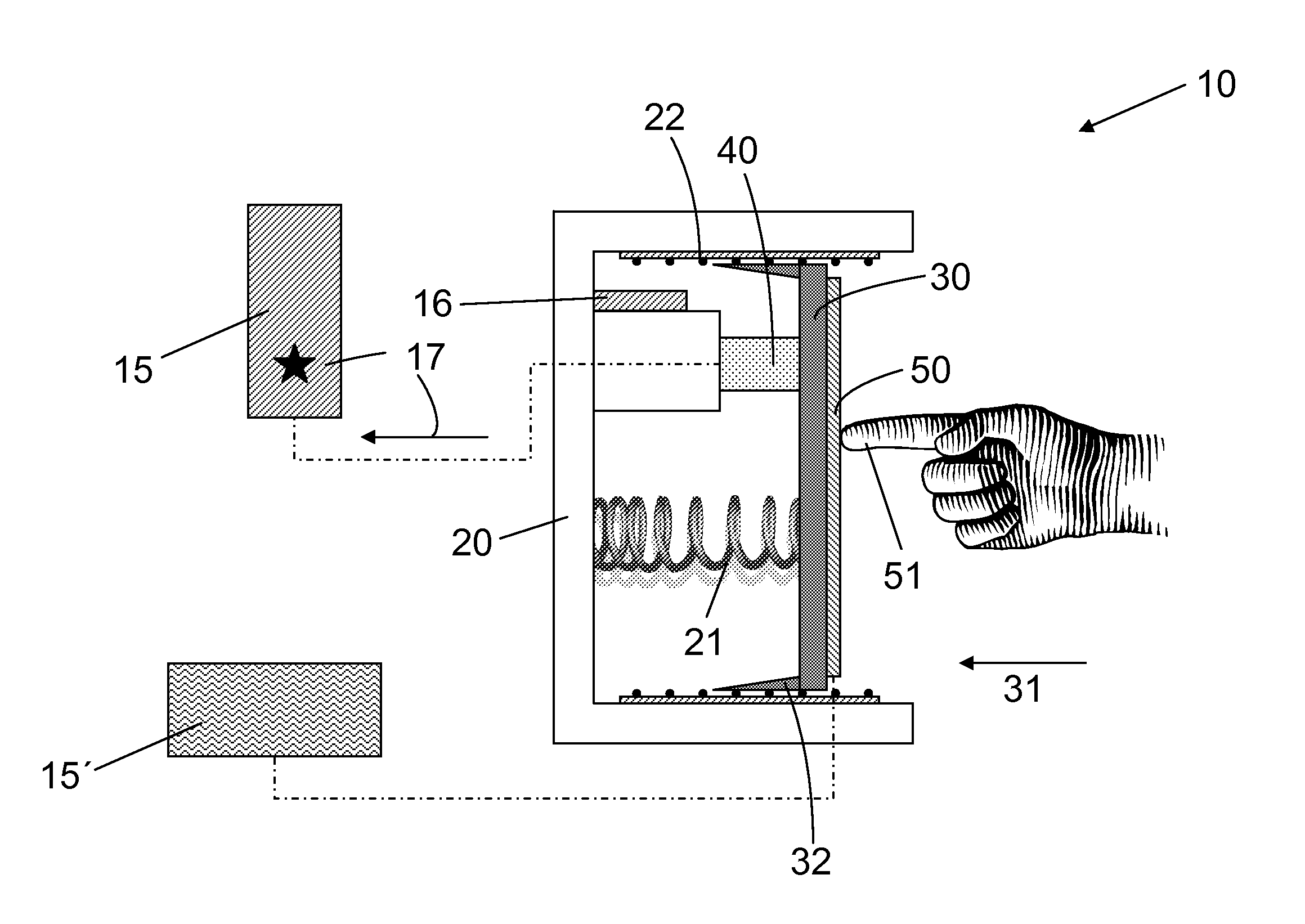
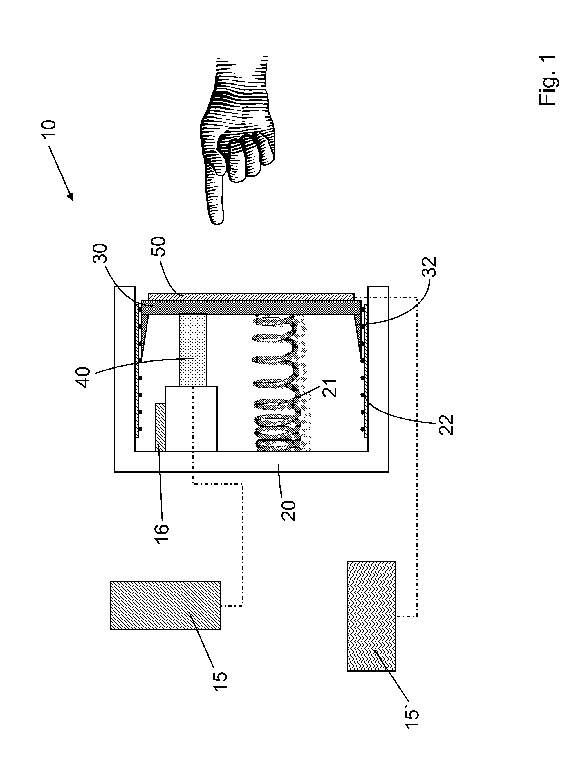
[0026]FIG. 1 shows a first advantageous embodiment of the switching device 10 for switching a consumer on and / or off, in particular a motor or the like in a motor vehicle. The switching device 10 has a housing 20, an operating element 30, a switch element 40 and a display 50. The display 50 is arranged on the operating element 30 and the switch element 40 can be activated by the operating element 30. By means of the switch element 40, at least one switch signal 17 can be generated for a control unit 15, 15′. According to the present invention, the switch element 40 is a piezoelectric switch. This piezoelectric switch is arranged in such a way that the switch signal 17 is generated on insertion 31 of the operating element 30 into the housing 20.

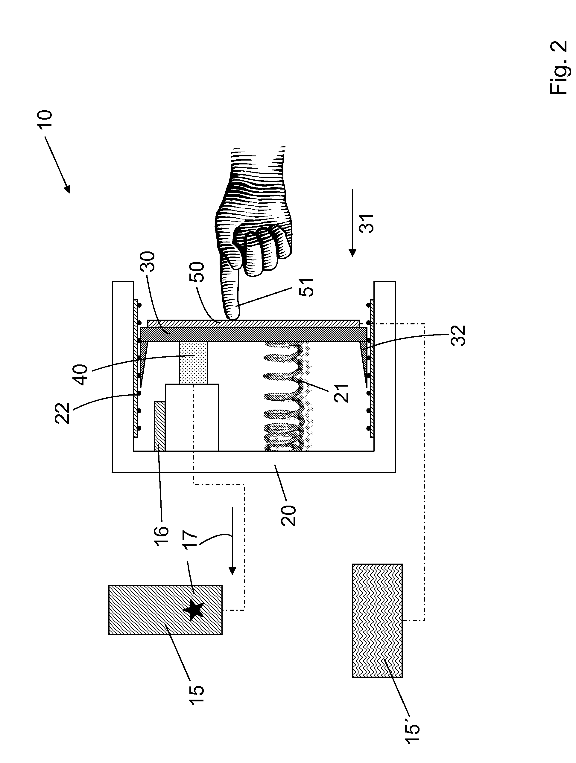
[0027]FIG. 2 illustrates the insertion 31 of the operating element 30 into the housing 20. It can be seen here that the operating element 30 is displaced with respect to the housing 20, with a force acting on the piezoelectric switch 40 to do ...


PUM


Abstract

The invention relates to a switch device (10), for switching a user on and off, in particular, a motor or similar in a vehicle, comprising a housing (20), an operating element (30), a switch element (40) and a display (50), wherein the display (50) is arranged on the operating element (30), the switch element (40) may be activated by the operating element (30) and at least one switch signal (117) for a control unit (15,15′) may be generated by means of the switch element (40). According to the invention, the switch element (40) is a piezo switch and the piezo switch is arranged such as to generate the switch signal (17) on pushing (31) the operating element (30) into the housing (20).

Description

TECHNICAL FIELD[0001]The present invention relates to a switching device for switching a consumer on and / or off, in particular a motor or the like in a motor vehicle, having a housing, an operating element, a switch element and a display, the display being arranged on the operating element, the switch element being activatable by the operating element, and at least one switch signal for a control unit can be generated by means of the switch element.BACKGROUND[0002]DE 101 64 558 A1 describes an ignition switch used for starting or turning off a motor vehicle engine. The ignition switch is located near a steering column and has a body movably arranged in a housing. In addition, a switch body keeping the movable body movable and serving to detect a shift in the movable body is arranged in the ignition switch. Furthermore, there is a display element for displaying a status of the vehicle in the vicinity of the movable body. With such emission switches, the driver pushes the movable body...

Claims


Application Information

Patent Timeline
IPC IPC(8): H01H57/00
CPCH03K17/965H03K17/964
Inventor MONIG, STEFANBRAUNER, CHRISTOFTHRONBERENS, STEFANFALKENBERG, ANDREASPOLAN, INGODYCKERS, HARALD
Owner HUF HULSBECK & FURST GMBH & CO KG
Why Eureka
Try Eureka