Disk brake

a technology of disc brake and friction pad, which is applied in the direction of braking elements, slack adjusters, actuators, etc., can solve the problems of uneven wear of friction pads, brake noise, and difficulty in arranging the return spring,

Active Publication Date: 2010-07-29
HITACHI ASTEMO LTD
View PDF12 Cites 20 Cited by
  • Summary
  • Abstract
  • Description
  • Claims
  • Application Information

AI Technical Summary

Benefits of technology

[0017]As recited hereinabove, according to the present invention, it will be easy to find the space for mounting the return spring between the back plate of the friction pads and

Problems solved by technology

However, since the return spring in the conventional art is structured as that the return spring in its thickness direction is oriented toward the circumferential direction of the disk, for example, in case that the caliper is a twin-bore, and/or in case that a friction detecting portion is provide

Method used


Image

  • Disk brake
  • Disk brake
  • Disk brake

Examples


Embodiment Construction

[0035]Hereinafter, a disk brake according to the embodiments of the present invention will be explained in detail with reference to the accompanying drawings.

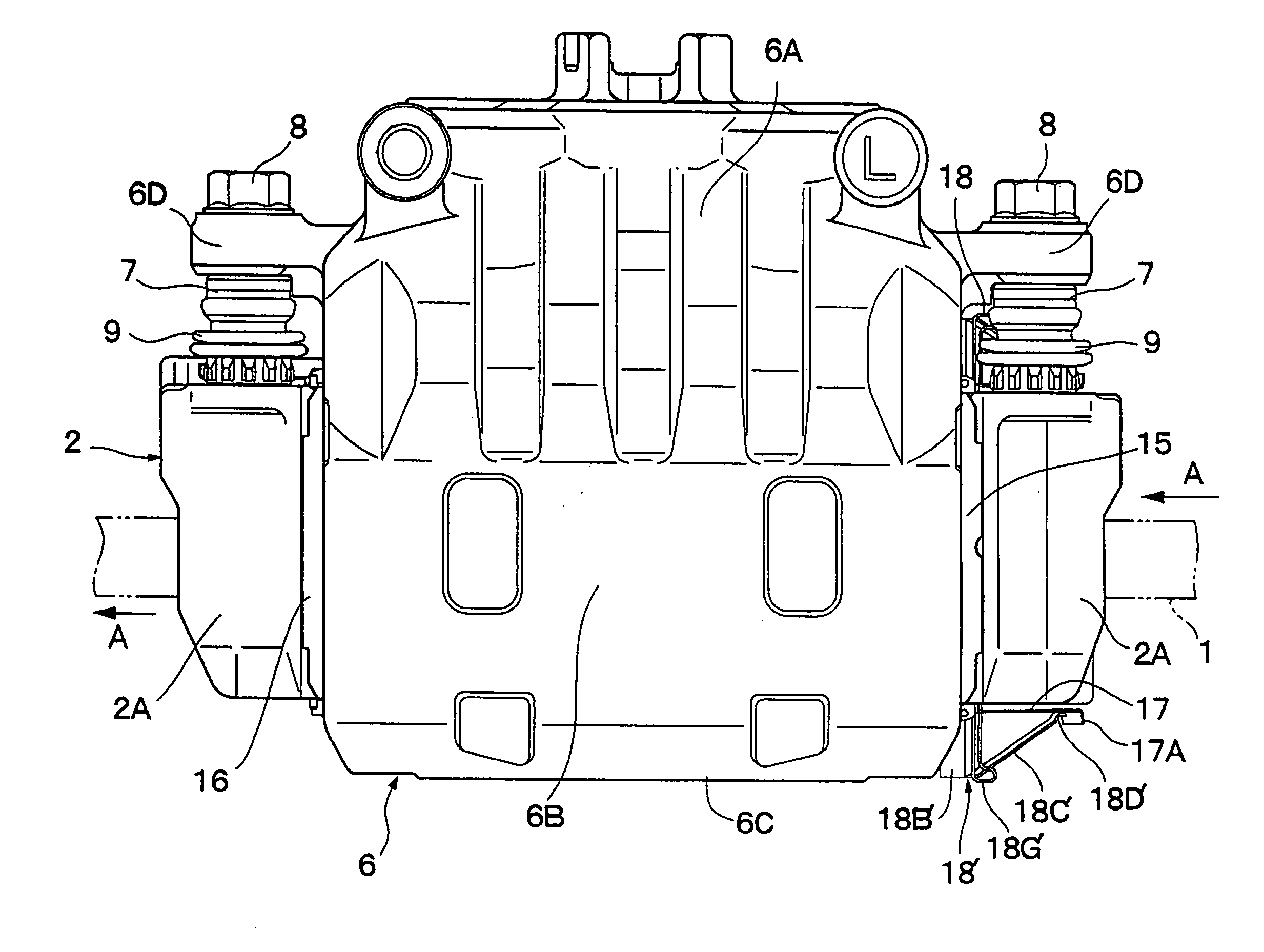
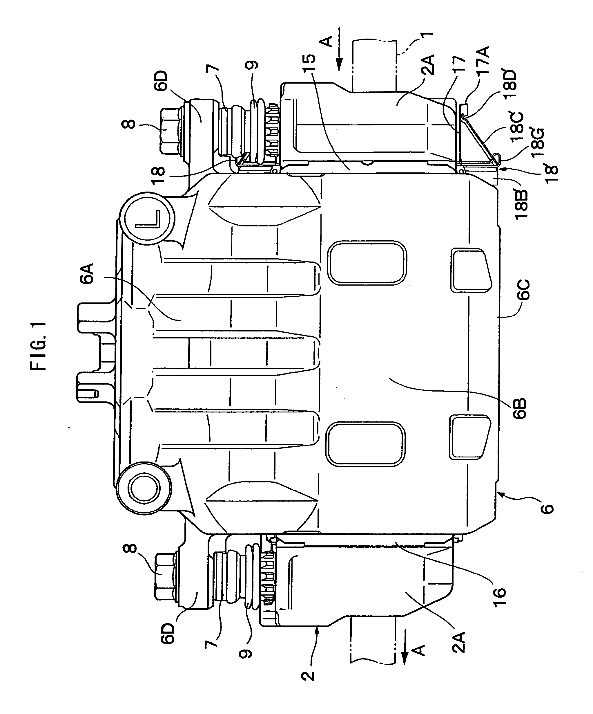
[0036]FIGS. 1 to 16 show the embodiments of the present invention. In these FIGS, a reference numeral 1 indicates a disk to be rotated. This disk 1 rotates with wheels (not shown) in an arrow A direction in FIG. 1 when, for example, a vehicle runs in a forward direction.

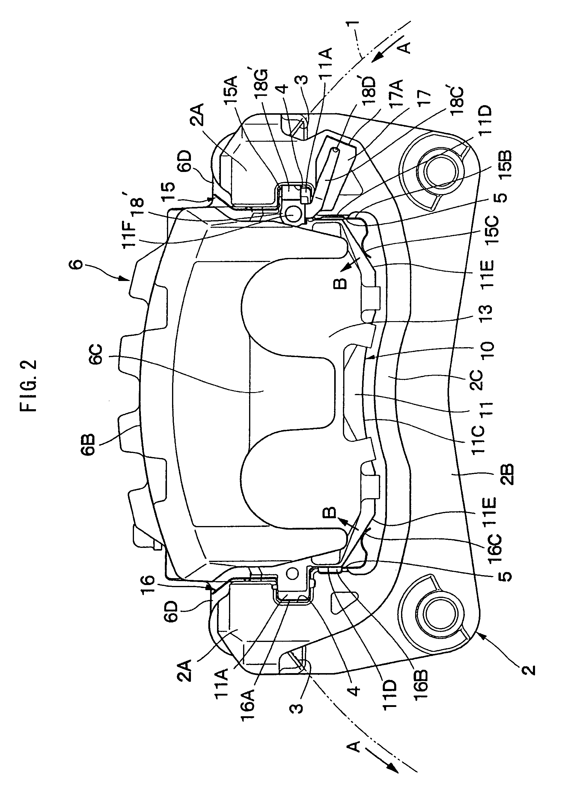
[0037]A reference numeral 2 is a mounting member as a carrier that is mounted on a non-rotating portion of the vehicle. This mounting member 2, as shown in FIGS. 1 and 2, comprises: a pair of arms 2A, 2A extending in the axial direction of the disk so that each of the arms 2A, 2A is separated from each other along the rotating direction (circumferential direction) of the disk 1, and extends over the outer periphery of the disk 1; a thick supporting portion 2B fixed to the non-rotating portion of the vehicle which is placed on the inner side of the disk 1 in such...


PUM


Abstract

There is provided a disk brake comprising: a mounting member axially extending over a disk periphery, the mounting member including a pad guide where a friction pad travels; a caliper; and a return spring between the friction pad and the mounting member and urges the friction pad into a return direction separating from the disk, wherein the return spring includes: a first extended portion where a base end side thereof is fixed to a back plate of the friction pad while a top end side thereof extends separating from the disk; and a second extended portion folded from the top end side of the first extended portion toward the mounting member, a top of the second extended portion extending to elastically abut to the side of the mounting member, and a plate thickness direction of the first extended portion extends to be approximately a radial direction of the disk.

Description

BACKGROUND OF THE INVENTION[0001]1. Field of the Invention[0002]The present invention relates to a disk brake that suitably applies braking force to a vehicle such as an automobile.[0003]2. Description of the Related Art[0004]In general, a disk brake provided at a vehicle such as an automobile comprises: a mounting member mounted on a non-rotating portion of the vehicle where the mounting member includes a pair of arms that is separated along a rotating direction of a disk and extends over the exterior of the disk in its axial direction; a caliper slidably provided at each of the arms of the mounting member; a pair of friction pads slidably supported by each of the arms of the mounting portion through a pad spring where the pair of friction pads are pressed toward the disk by means of the caliper; and the like.[0005]In the conventional disk brake categorized by this type, when a driver performs braking operation, a piston provided on the inner side of the caliper is adapted to slida...

Claims


Application Information

Patent Timeline
IPC IPC(8): F16D55/22
CPCF16D65/097F16D65/0978F16D66/02F16D2127/02
Inventor HAYASHI, SHIGERUTAZAKI, MASATOSHI
Owner HITACHI ASTEMO LTD
Why Eureka
Try Eureka