Visual presenter

Inactive Publication Date: 2010-07-29
ELMO CO LTD
View PDF4 Cites 8 Cited by
  • Summary
  • Abstract
  • Description
  • Claims
  • Application Information

AI Technical Summary

Benefits of technology

[0010]Therefore, an object of the present invention is to provide a visual presenter which can enlarge the imaging area without use of the mounting by a simple operation and has good usability.
[0011]Another object of the invention is to provide a visual presenter which can image only the material when the imaging area is enlarged, preventing anything other than the material from being imaged together with the material.
[0013]In the above-described construction, an imaging distance from the camera head to the material on the base installation surface is longer by the spacing between the first and second support shafts when the first horizontal part assumes the horizontal position and the second horizontal part assumes the horizontal forward position than when the first horizontal part assumes the downwardly extending position and the second horizontal part assumes the horizontal backward position. Consequently, the imaging area of the camera head can be enlarged.
[0014]Moreover, the location of the camera head is moved forward by the spacing between the first and second support shafts upon enlargement of the imaging area of the camera head. Consequently, the base front can be prevented from being imaged together with the material.

Problems solved by technology

Thus, the conventional visual presenter 100 is not convenient for users.
This poses a problem.

Method used


Image

  • Visual presenter
  • Visual presenter
  • Visual presenter

Examples


Embodiment Construction

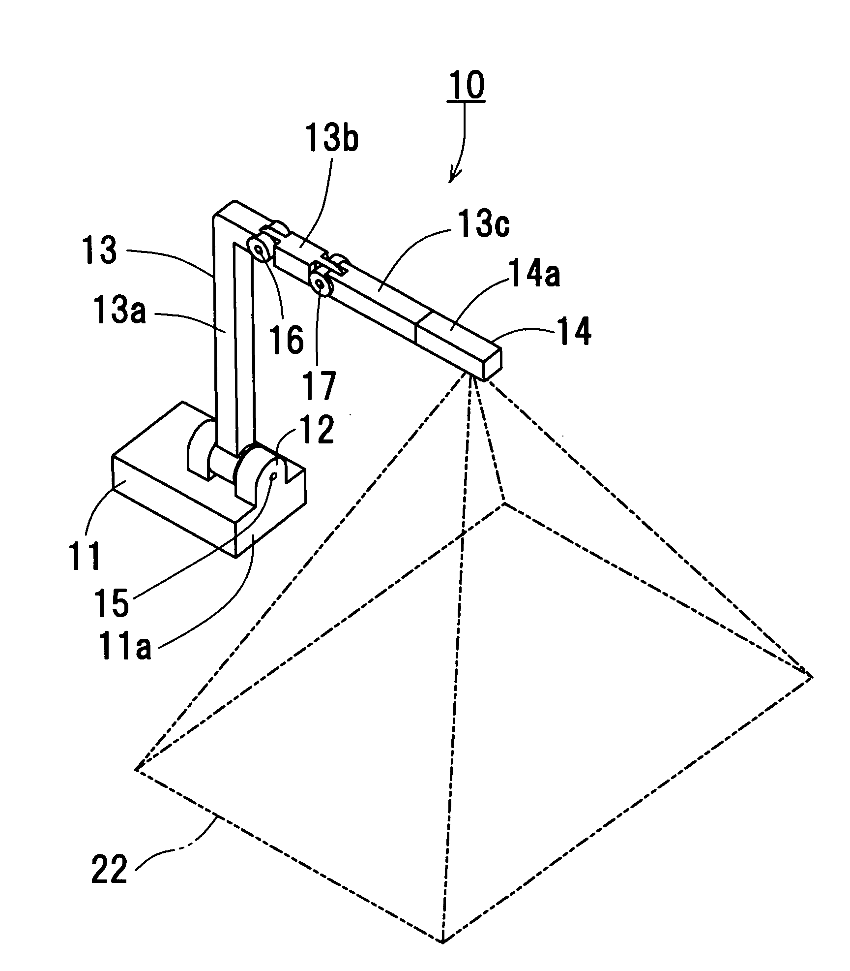
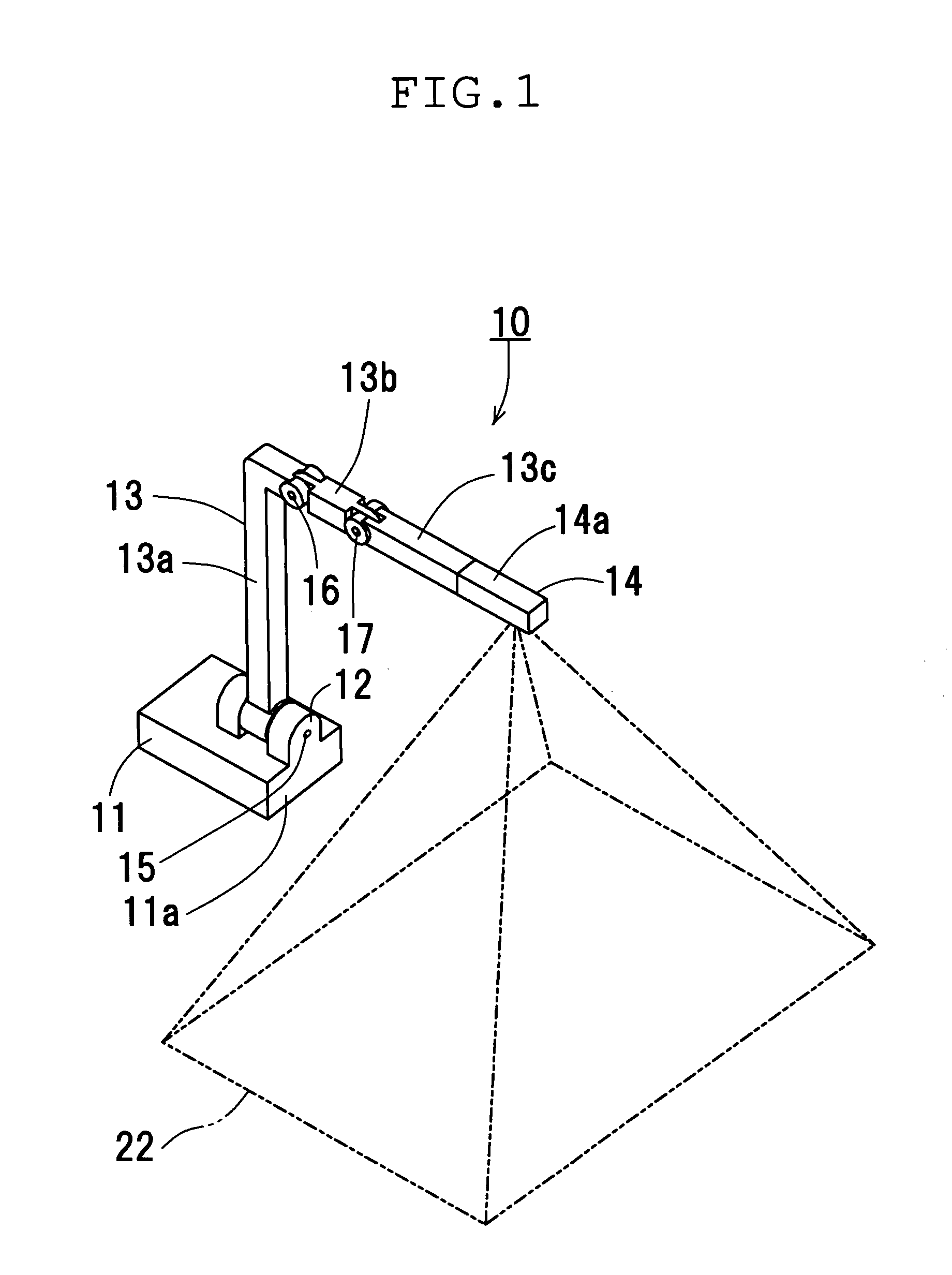
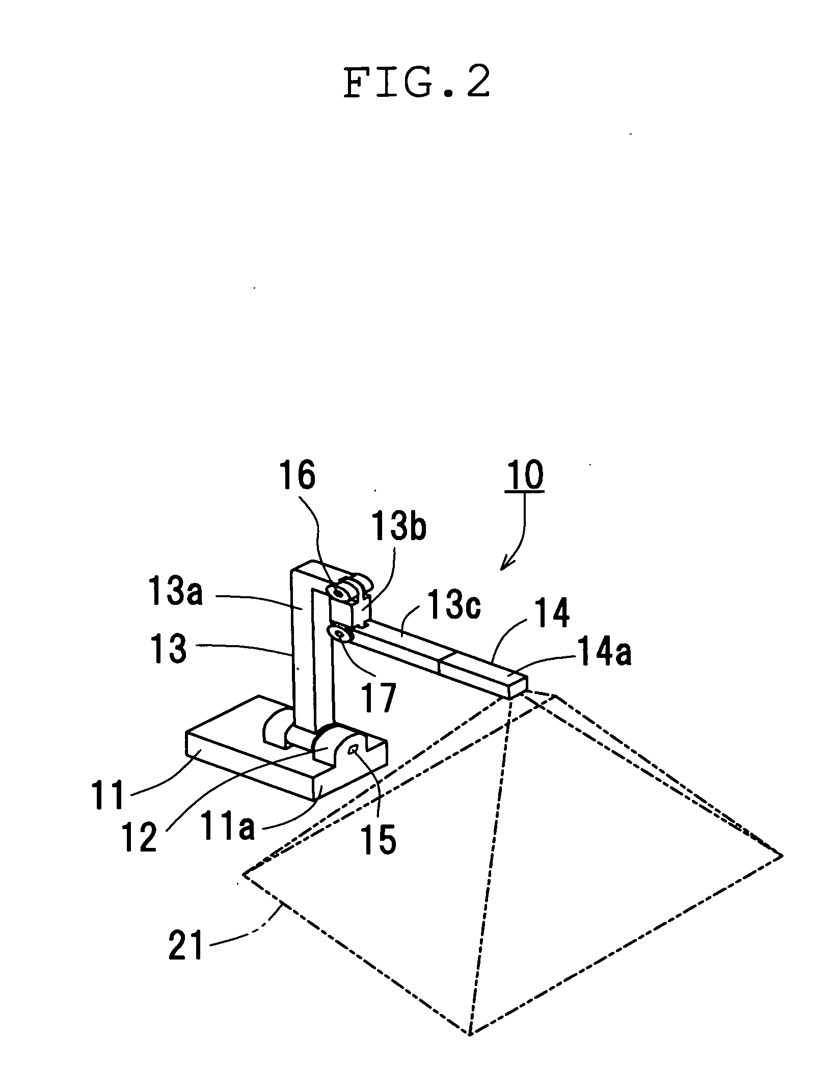
[0027]One embodiment of the present invention will be described with reference to FIGS. 1 to 8 of the accompanying drawings. Referring to FIG. 1, a visual presenter of the embodiment is shown. The visual presenter 10 includes a base 11, a pedestal 12, a support column 13 and a camera head 14. The base 11 is generally rectangular in planar shape and includes a front 11a on which the pedestal 12 is mounted. A control circuit unit (not shown) is incorporated in the base 11. The base 11 has a rear (not shown) provided with terminals which are used to connect the visual presenter 10 to a TV monitor, a video projector 10 and the like.

[0028]The support column 13 has a hollow construction and is composed of an upright part 13a, a first horizontal part 13b extending ahead of the base 11 horizontally from an upper end of the upright part 13a, and a second horizontal part 13c extending ahead of the base 11 horizontally from the first horizontal part 13b. Wire harnesses (not shown) are inserted...


PUM


Abstract

A visual presenter includes a base, a column support including an upright part and a horizontal part, and a camera head mounted on a distal end of the horizontal part. The horizontal part includes first and second horizontal parts. The first horizontal part is mounted on a first support shaft further mounted on the upright part, so as to be pivotable between a downwardly extending position and a horizontal position. The second horizontal part is mounted on a second support shaft further mounted on an end of the first horizontal part located opposite the first support shaft side, so as to be pivotable between a horizontal backward position and a horizontal forward position.

Description

CROSS-REFERENCE TO RELATED APPLICATIONS[0001]This application is based on and claims the benefit of priority from the prior Japanese Patent Application No. 2009-14846, filed on Jan. 27, 2009, the entire contents of which are incorporated herein by reference.BACKGROUND[0002]1. Field[0003]The present invention relates to a visual presenter in which a camera head is provided on a distal end of a column support standing on a base, and a material such as document or model placed in front of the base is imaged by the camera head, and an obtained-image is reproduced by a monitor television or projected on a screen by a video projector.[0004]2. Related Art[0005]Japanese patent application publication, JP-A-2008-193391 discloses one type of visual presenter. FIGS. 9 and 10 show the disclosed visual presenter 100. As shown, a support column 102 is mounted on a base 101 so as to stand from the base 101. The support column 102 has a distal end on which a camera head 103 is mounted.[0006]The sup...

Claims


Application Information

Patent Timeline
IPC IPC(8): F16M11/10
CPCF16M11/10F16M11/12F16M11/2057F16M11/38H04N1/00519H04N2201/0448H04N1/195H04N1/19594H04N2201/0436H04N2201/0446H04N1/00559
Inventor YAMAKOSE, HIROSHIONO, SHINJIMARUYAMA, KENICHI
Owner ELMO CO LTD
Why Eureka
Try Eureka