Marine vessel propulsion system and marine vessel including the same

a technology for marine vessels and propulsion systems, applied in marine propulsion, vessel construction, instruments, etc., can solve the problems of overly complex structure, require somewhat more complicated operations, and complex structure of marine vessel propulsion systems, so as to improve operability and improve operability

Active Publication Date: 2010-07-29
YAMAHA MOTOR CO LTD
View PDF11 Cites 25 Cited by
  • Summary
  • Abstract
  • Description
  • Claims
  • Application Information

AI Technical Summary

Benefits of technology

[0013]In the thus arranged marine vessel propulsion system, the target pivoting speed and target travel speed of the hull are set based on the positions of the first and second operation levers. The steering angles, shift states, and propulsive forces of the first and second propulsion devices are then controlled according to the set target pivoting speed and target travel speed. That is, not only the shift states and propulsive forces but also the steering angles follow the positions of the first and second operation levers. This arrangement allows the propulsive forces of the propulsion devices to be used effectively when the hull pivots or turns (pivots while moving forward or backward). This allows the behavior of the hull to be changed quickly and highly responsively. As a result, the movement of the marine vessel can be finely controlled.
[0036]Another preferred embodiment of the present invention provides a marine vessel including a hull and a marine vessel propulsion system mounted on the hull and having the above-described features. This arrangement can improve the operability when finely controlling the movement of the marine vessel while preventing the marine vessel propulsion system from having a complex structure.

Problems solved by technology

That is, the related art above requires two operation levers and a cross-shaped key to be provided separately, resulting in the marine vessel propulsion system having a complex structure.
This results in an overly complex structure and requires somewhat more complicated operations due to an increase in the number of operation systems.

Method used


Image

  • Marine vessel propulsion system and marine vessel including the same
  • Marine vessel propulsion system and marine vessel including the same
  • Marine vessel propulsion system and marine vessel including the same

Examples


first preferred embodiment

[0063]First, the structure of a marine vessel propulsion system according to a first preferred embodiment of the present invention will hereinafter be described with reference to FIGS. 1 to 5.

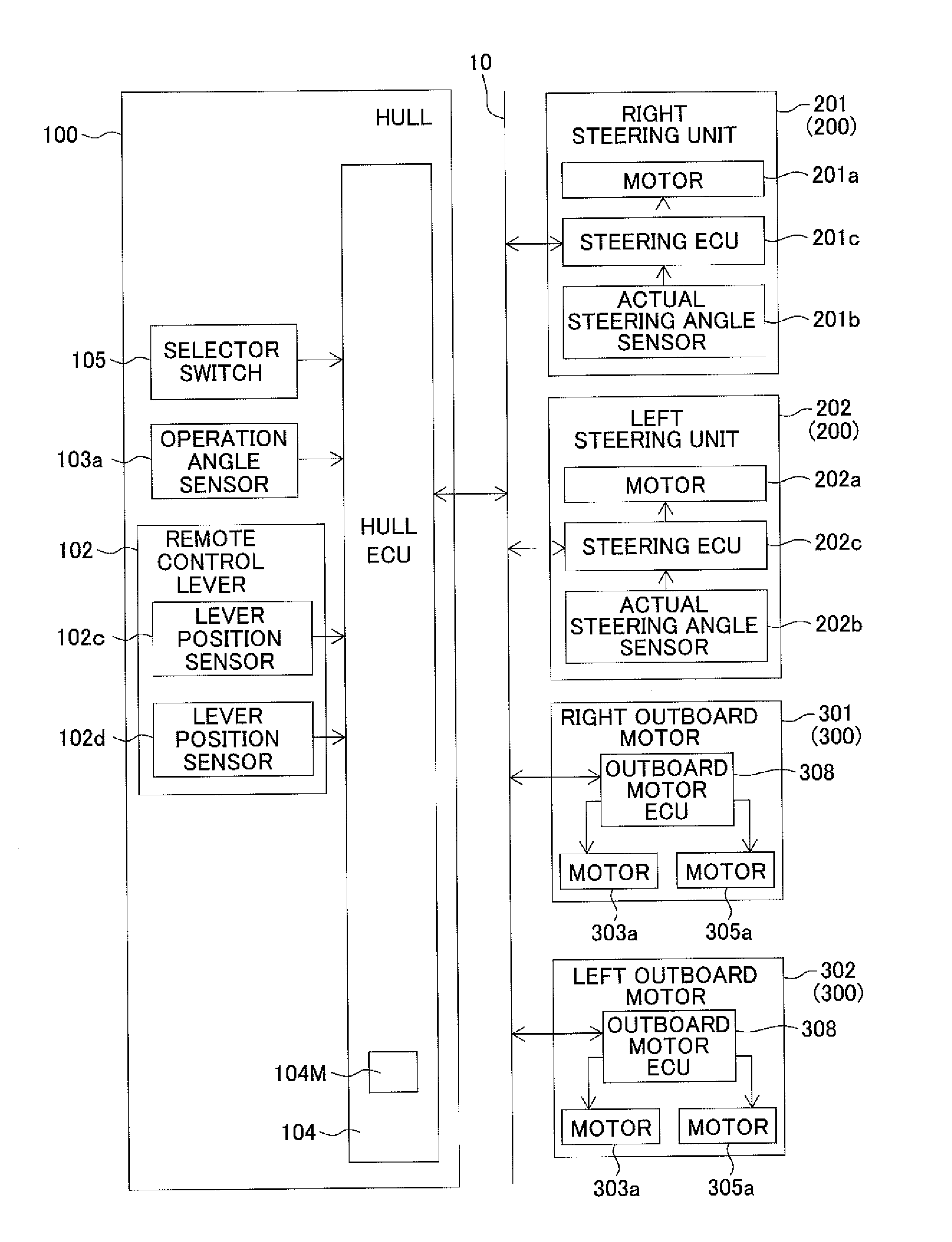
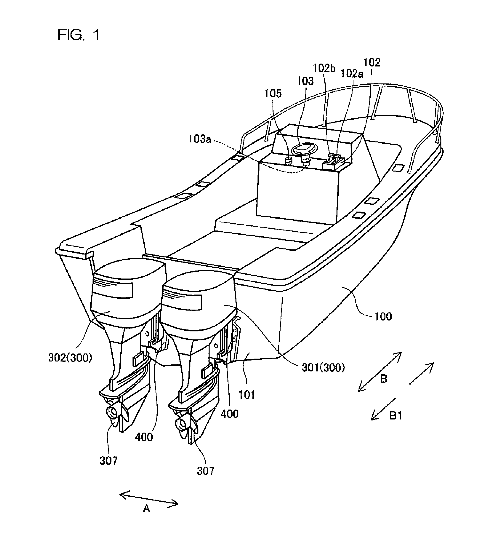
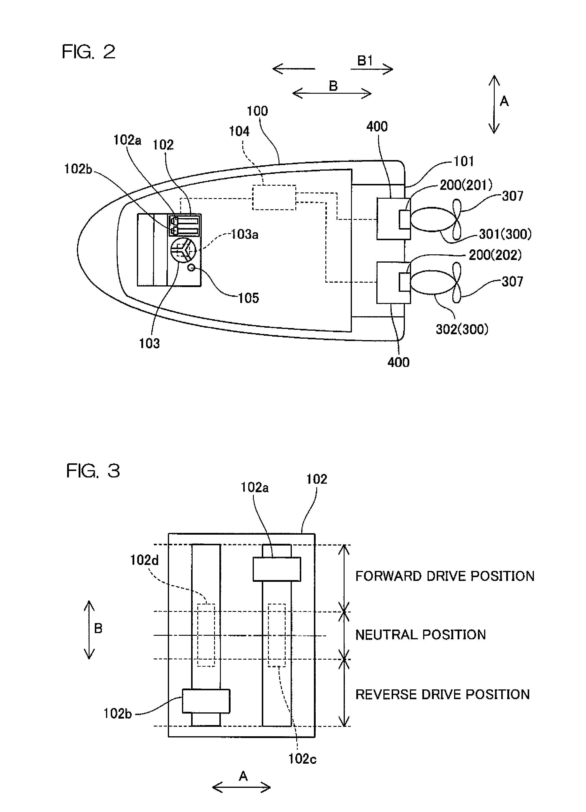
[0064]Two outboard motors 300 (right outboard motor 301 and left outboard motor 302) are mounted at the stern 101 of a hull 100 via two steering units 200 (right steering unit 201 and left steering unit 202) (see FIGS. 2 and 5). A remote control lever 102, a steering operation mechanism 103 such as a steering wheel, a hull ECU (Electronic Control Unit) 104, a trim switch (not shown), and the like are arranged on the hull 100. The remote control lever 102 is arranged to be operated by a marine vessel maneuvering operator to control switching the throttle opening degrees and shift states of the outboard motors 300. The steering operation mechanism 103 is arranged to be operated by the operator to change the heading direction of the hull 100. The hull ECU 104 is programmed to control the marine ve...

second preferred embodiment

[0140]In a second preferred embodiment of the present invention, the control under the assisted marine vessel maneuvering mode is different from that in the above-described first preferred embodiment. Hence, the second preferred embodiment will be described by referring again to FIGS. 1 to 5 and redundant descriptions will be omitted.

[0141]The control of the marine vessel propulsion system according to the second preferred embodiment under the assisted marine vessel maneuvering mode will be described with reference to FIGS. 21 and 22. It is noted that the “propulsive direction” indicated by the arrows in FIG. 21 is a direction of a propulsive force applied to the hull 100 by the right and left outboard motors 301 and 302. The length of each arrow represents the magnitude of a propulsive force by the right and left outboard motors 301 and 302.

[0142]In the assisted marine vessel maneuvering mode, the steering angles, shift states, and throttle opening degrees of the respective outboar...


PUM


Abstract

A marine vessel propulsion system includes first and second propulsion devices arranged to be mounted on a hull so as to enable a steering angle to change, a first operation lever arranged to be operated by a marine vessel maneuvering operator to control the first propulsion device to have a shift state selected from among a forward drive state, a neutral state, and a reverse drive state and to control a power output of the first propulsion device, a second operation lever arranged to be operated by the marine vessel maneuvering operator to control the second propulsion device to have a shift state selected from among a forward drive state, a neutral state, and a reverse drive state and to control a power output of the second propulsion device, a first lever position sensor arranged to detect a position of the first operation lever, a second lever position sensor arranged to detect a position of the second operation lever, and a control unit. The control unit is programmed to set a target pivoting speed according to the positions of the first and second operation levers relative to each other and set a target travel speed according to amounts of displacement of the first and second operation levers with respect to neutral positions. The control unit is also programmed to control the steering angles, shift states, and propulsive forces of the respective first and second propulsion devices such that the hull pivots at the target pivoting speed and travels at the target travel speed.

Description

BACKGROUND OF THE INVENTION[0001]1. Field of the Invention[0002]The present invention relates to a marine vessel propulsion system including operation levers arranged to be operated for controlling the respective shift states of multiple propulsion devices. The present invention also relates to a marine vessel including such a system.[0003]2. Description of the Related Art[0004]There has been known a marine vessel propulsion system including operation levers arranged to be operated by a marine vessel maneuvering operator to control the respective shift states of multiple propulsion devices. One example of such a propulsion device is an outboard motor.[0005]Such a marine vessel propulsion system includes, for example, two outboard motors mounted on a hull. The two outboard motors are coupled to each other with a tie bar and arranged to have substantially the same steering angle. The marine vessel propulsion system further includes two operation levers corresponding to the two respect...

Claims


Application Information

Patent Timeline
Patent Type & Authority Applications(United States)
IPC IPC(8): G05D1/00B63H21/21B60W10/20B60W10/04G05D1/02B63H25/00B63H20/00
CPCB63H25/42B63H25/52Y02T10/56Y02T10/40
Inventor NOSE, YUKINORIINAI, TOSHIYAICHIKAWA, YOSHIYUKIMIZUTANI, MAKOTO
Owner YAMAHA MOTOR CO LTD
Why Eureka
Try Eureka