Rear fender structure for motorcycle and motorcycle

a rear fender and motorcycle technology, applied in the direction of roofs, cycle equipments, vehicular safety arrangments, etc., can solve the problems of complicated structure (shape and arrangement) of parts, problems such as the above mentioned conventional rear fender structure, and achieve the effect of reducing the number of mounting parts, ensuring the rigidity of the rear fender, and simplifying the mounting operation

Active Publication Date: 2010-08-05
SUZUKI MOTOR CORP
View PDF14 Cites 14 Cited by
  • Summary
  • Abstract
  • Description
  • Claims
  • Application Information

AI Technical Summary

Benefits of technology

[0012]The present invention has been made in view of such actual circumstances, and an object thereof is to sufficiently secure a rigidity of a rear fender without complicating a structure of parts. Further, the present invention has an object to realize a simplification of mounting operation and the like while sufficiently securing a rigidity of a rear fender and reducing the number of mounting parts.

Problems solved by technology

However, the aforementioned conventional rear fender structure has problems as described below.
Specifically, at first, there is a problem that a structure (shape and arrangement) of parts becomes complicated.
Further, cables and the like of various electrical components disposed on an internal surface of the rear fender are exposed to the outside, which gives an impression that the arrangement of parts is complicated, and further, it is hard to say that it is preferable in terms of security.
Further, there is a problem that the number of mounting parts is increased.
Further, a bracket is made of aluminum or iron, so that it may amplify a vibration, ascribable to its own weight, which creates a problem that an unnecessary load may be imposed on the rear fender.
In such a case, the weight becomes heavy, which becomes a main cause to amplify the vibration.

Method used


Image

  • Rear fender structure for motorcycle and motorcycle
  • Rear fender structure for motorcycle and motorcycle
  • Rear fender structure for motorcycle and motorcycle

Examples


Embodiment Construction

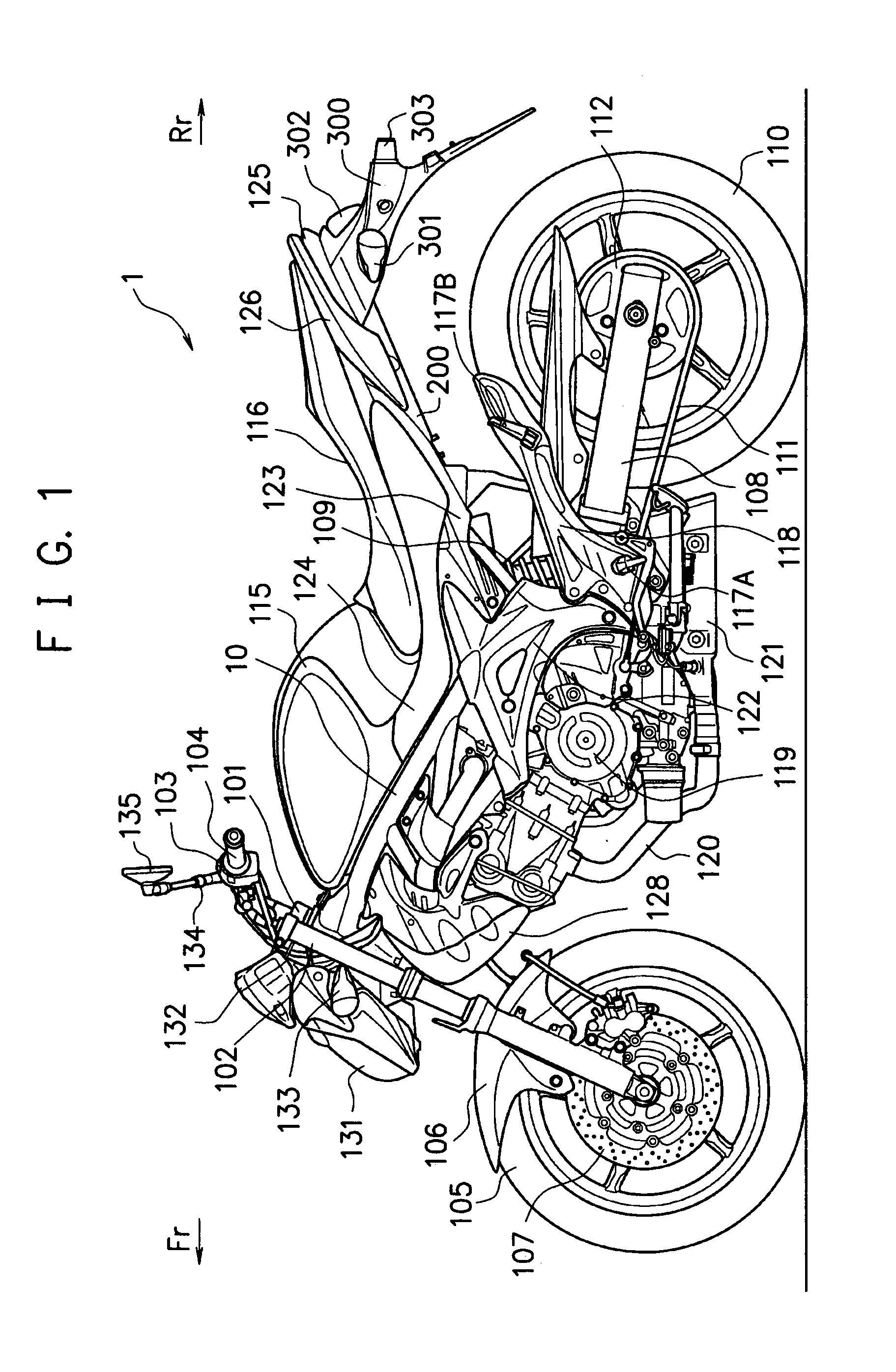
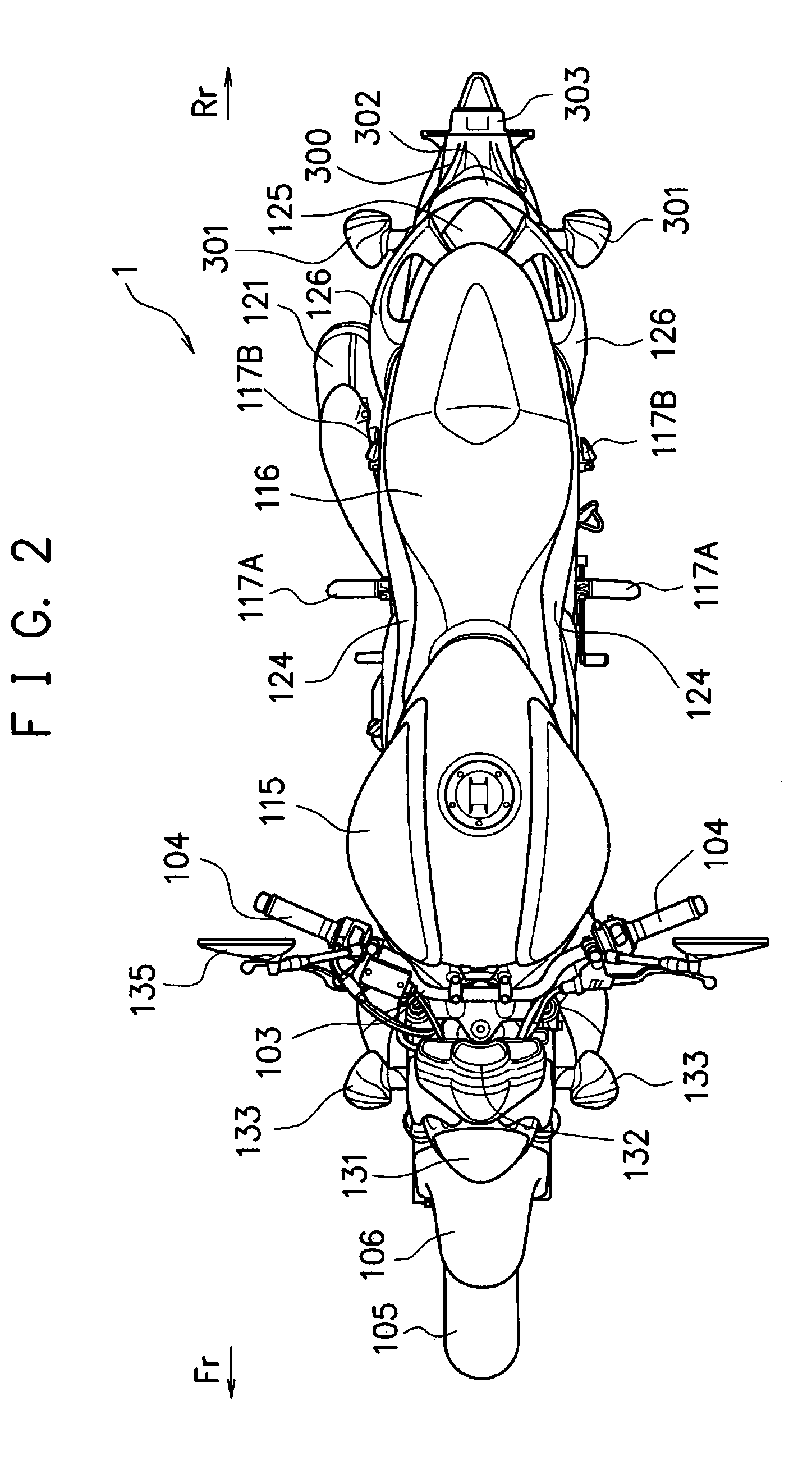
[0038]Hereinafter, a preferred embodiment of the present invention will be described based on the drawings. FIGS. 1, 2, 3A and 3B are respectively a side view, a plan view, a front view and a rear view of a motorcycle 1 including a rear fender structure for motorcycle according to the present invention. At first, a schematic structure of the motorcycle 1 will be described by using FIG. 1 to FIGS. 3A and 3B. Note that in these drawings, a front of a vehicle and a rear of the vehicle are indicated by an arrow Fr and an arrow Rr, respectively.

[0039]1>

[0040]In FIG. 1, a main frame 10 is one of main members that constitute a skeletal structure of a vehicle body frame. The main frame 10 is made of a pair of left and right steel or aluminum alloy material, and front portions thereof are joined to a steering head pipe 101. Left and right two front forks 102 are supported to be able to pivot left and right by the steering head pipe 101. A handle bar 103 is fixed to upper ends of the front fo...


PUM


Abstract

A rear rear-fender bracket integrally coupled to an upper portion and a lower portion of a rear rear-fender that is mounted to a rear portion of a vehicle body of a motorcycle, extending rearward and downward, and covering a rear wheel from upward and rearward, is provided to the rear rear-fender, and forms, with an internal surface of the rear rear-fender, a closed space having an inverted triangular shape when viewed from a vehicle side in which a space is gradually narrowed from an upper portion to a lower portion. Further, at the time of mounting, the rear rear-fender and the rear rear-fender bracket are coupled by being screwed together by rear winkers on sides of the vehicle (long holes). Further, a lower portion of the rear rear-fender and a lower portion of the rear rear-fender bracket are coupled by being screwed together by a license plate mounting bracket.

Description

CROSS-REFERENCE TO RELATED APPLICATIONS[0001]This application is based upon and claims the benefit of priority of the prior Japanese Patent Application No. 2009-022782, filed on Feb. 3, 2009, the entire contents of which are incorporated herein by reference.BACKGROUND OF THE INVENTION[0002]1. Field of the Invention[0003]The present invention relates to a rear fender structure for motorcycle and a motorcycle, and more specifically to a structure relating to a security of rigidity and the like of a rear fender.[0004]2. Description of the Related Art[0005]In a motorcycle, a rear fender is mounted to a rear frame of a vehicle body frame by being fixed by bolts and the like. In recent years, it is often the case that a rear fender has a thin shape in terms of designing, and heavy objects such as a license plate and a license plate lamp are mounted to the rear fender at the rear thereof in an overhang state. Accordingly, a rigid member made of an aluminum or iron plate is mounted to such ...

Claims


Application Information

Patent Timeline
Patent Type & Authority Applications(United States)
IPC IPC(8): B60R19/00
CPCB62J15/00
Inventor YAMAMOTO, TAKAYO
Owner SUZUKI MOTOR CORP
Why Eureka
Try Eureka