Pneumatic tire

a technology of pneumatic tires and slits, which is applied in the direction of vehicle components, non-skid devices, transportation and packaging, etc., can solve the problems of large space provided between the slits, inability to prevent deviated wear from being generated, and easy generation of deviated wear along the circumferential direction of the tire in this region. to achieve the effect of preventing deviated wear

Active Publication Date: 2006-05-25
TOYO TIRE & RUBBER CO LTD
View PDF6 Cites 11 Cited by
  • Summary
  • Abstract
  • Description
  • Claims
  • Application Information

AI Technical Summary

Benefits of technology

[0016] According to the above structure, since the width of the root of the taper cut portion connected to the bridge portion is 2 mm or more, the root of the taper cut portion connected to the bridge portion

Problems solved by technology

According to the taper cut portion 15, however, it is not possible to sufficiently prevent the deviated wear from being generated.
Further, as shown in FIG. 6, if the tip end 18 is formed with the taper cut portion 15, a space provided between the slits becomes large, and there is a problem that deviated wear is easily generated along the circumfer

Method used


Image

  • Pneumatic tire
  • Pneumatic tire
  • Pneumatic tire

Examples


examples

[0043] Next, to concretely show the structure and the effect of the present invention, the deviated wear resistance was evaluated. This evaluation will be explained below.

[0044] First, test tires of the following examples of the invention (tire size: LT265 / 75R166PR) were prepared, the tread surface of each tire was allowed to become worn equally in the circumferential direction of the tire until the height of the taper cut portion became half. Then, the test tires were mounted on an actual vehicle (4800cc four-wheel drive vehicle, and two passengers rode), air pressure was 350 kPa, and the vehicle was allowed to run 12,000 km through general road. After the running, an amount of step of every block generated due to wear was measured, and the deviated wear resistance was evaluated. Two tires were prepared for each specification.

examples 1 and 2

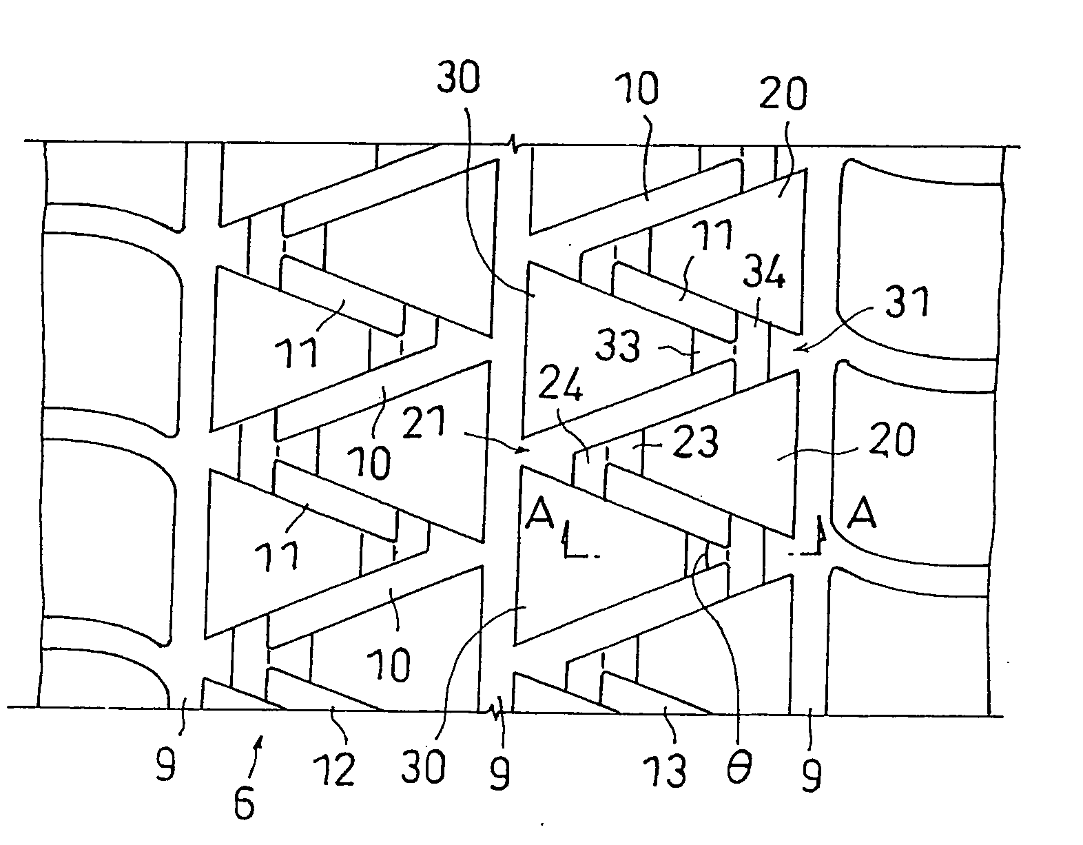
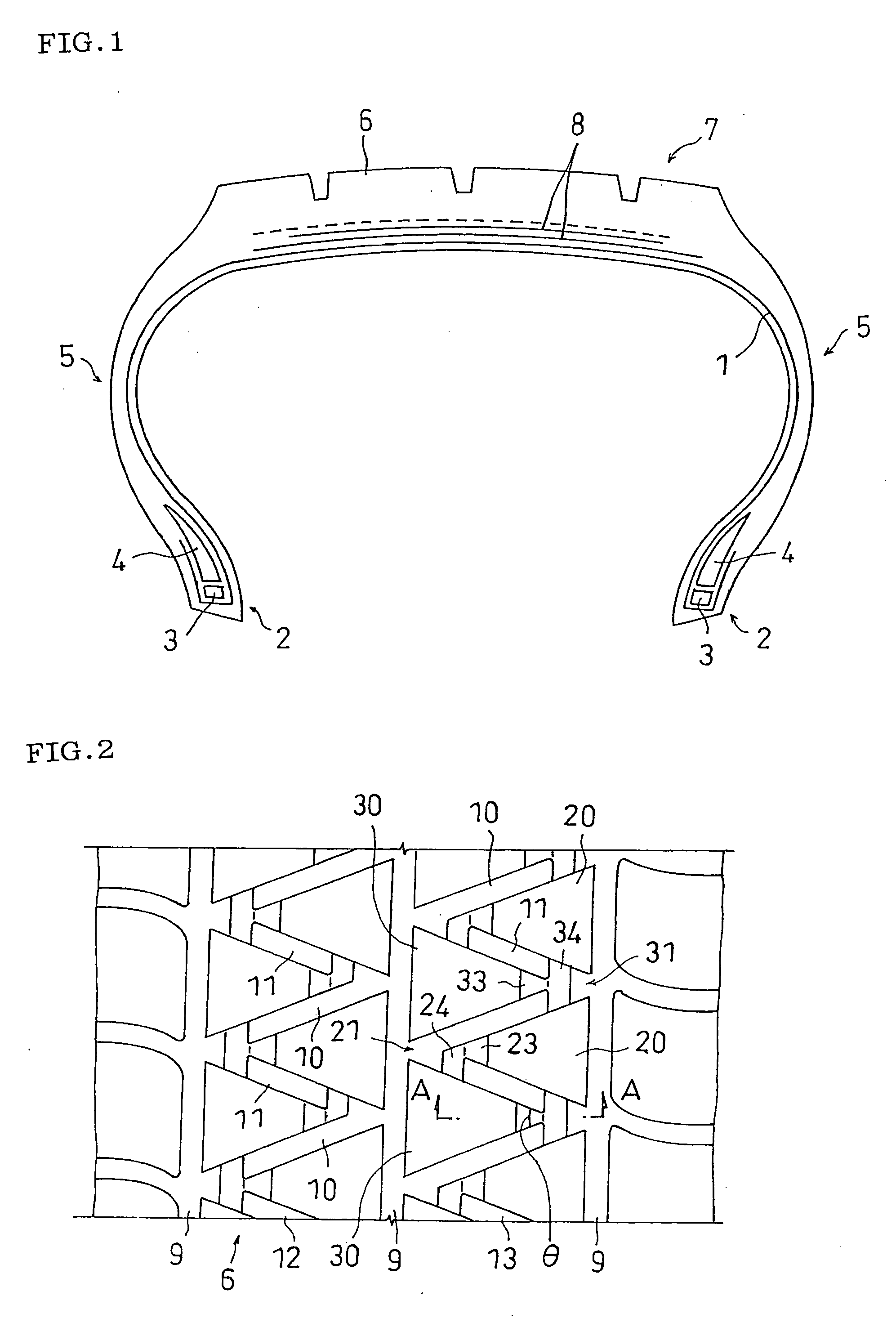
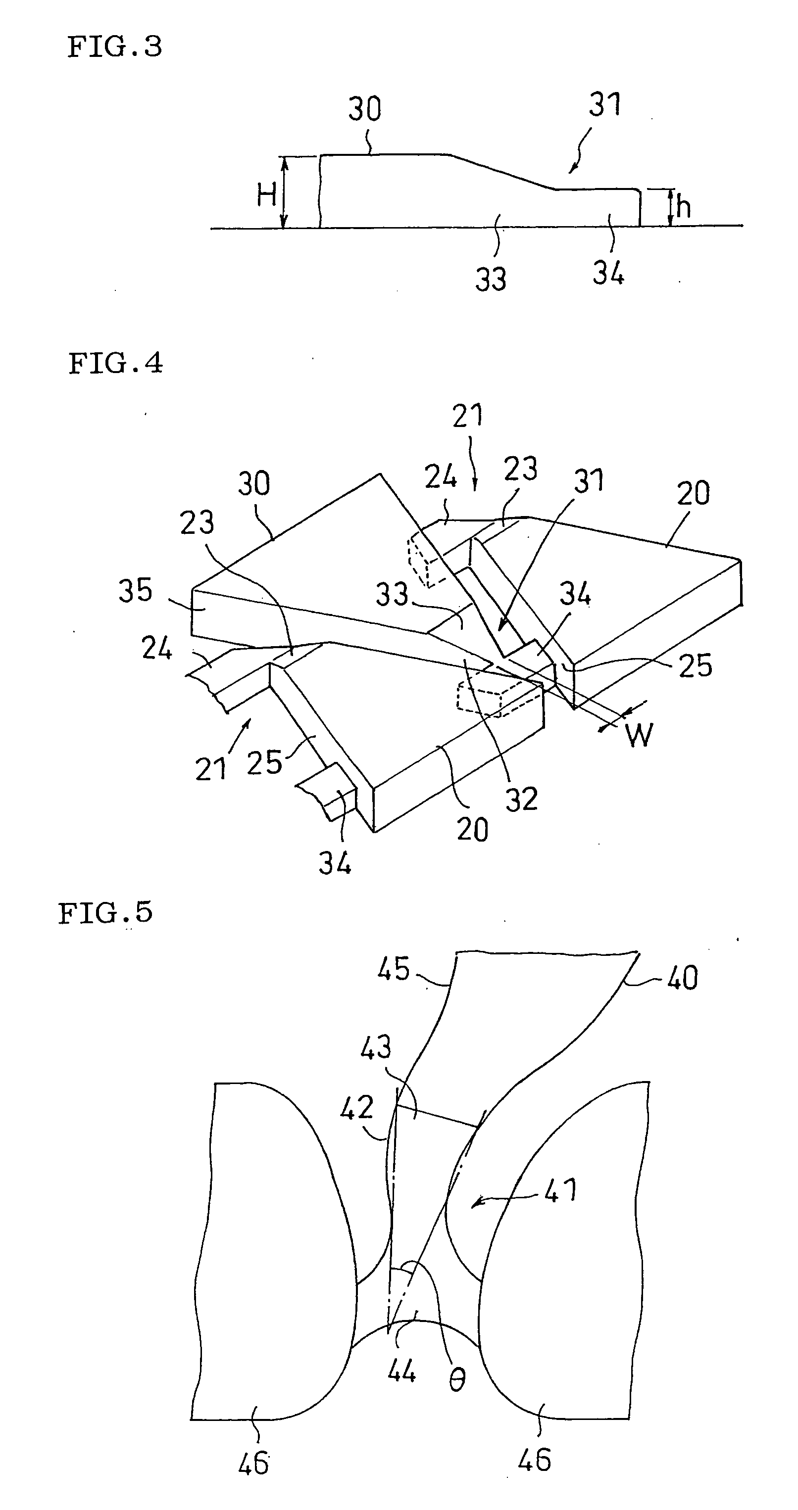
[0046] As shown in FIGS. 2 to 4, test tires were prepared as the examples 1 and 2 of the invention. The test tires are the same as those of the comparative example except that the tread surface is formed with a block line comprising blocks formed at their tip ends with taper cut portions and bridge portions. The land portion height of the bridge portion is 25% of the land portion height of the block. In the example 1, the block formed on the tread surface is connected to a sidewall surface located one of sides of the tip end like the block 20 shown in FIGS. 2 and 4. In the example 2, the block formed on the tread surface is connected to the sidewall surfaces located on both sides of the tip end like the block 30 shown in FIGS. 2 to 4.

[0047] A result of evaluation is shown in Table 1.

TABLE 1Amount of step (mm)MinimumMaximumBridge portionvaluevalueComparativeNo bridge portion1.62.0ExampleExample 1Bridge portion is0.91.4connected to sidewallsurface on one sideExample 2Bridge portion...


PUM


Abstract

It is an object of the present invention to provide a pneumatic tire capable of securing rigidity of a tip end of a block, and effectively preventing deviated wear of a tread surface. In a tread surface of a pneumatic tire formed with a block 30 having a tip end 31 which is tapered as viewed from above, and a block 20 having a sidewall surface 25 opposed to a sidewall surface 32 of the block 30, the tip end 31 of the block 30 is provided with a taper cut portion 33 whose land portion height is gradually reduced toward its tip end side, and a bridge portion 34 which is connected to the sidewall surface 25 of the block 20 at a substantially constant land portion height from the tip end of the taper cut portion 33.

Description

BACKGROUND OF THE INVENTION [0001] 1. Field of the Invention [0002] The present invention relates to a pneumatic tire whose tread surface is formed with a block line comprising a plurality of blocks. [0003] 2. Description of the Related Art [0004] Usually various tread patterns are formed on tread surfaces of pneumatic tires in accordance with required tire performance and using condition. Among the various tread patterns, a tread pattern called block type has a plurality of blocks divided by a plurality of grooves, and this tread pattern is known as one having excellent snow-covered road performance, drainage performance and traction performance. [0005]FIG. 6 is a plan view showing one example of a conventional block type tread pattern. A tread surface 16 is formed with circumferential grooves 9 extending in the circumferential direction of the tire, inclined grooves 10 and inclined grooves 11 extending obliquely with respect to the circumferential direction of the tire, and block ...

Claims


Application Information

Patent Timeline
IPC IPC(8): B60C11/03
CPCB60C11/11B60C11/1369B60C11/1384Y10S152/902
Inventor MIYAZAKI, TETSUJI
Owner TOYO TIRE & RUBBER CO LTD
Why Eureka
Try Eureka